EasyManuals Logo

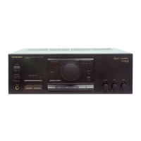
Technics SU-X955 Service Manual

Technics SU-X955
26 pages
To Next Page IconTo Next Page
To Previous Page IconTo Previous Page
Page #6 background imageLoading...
Page #6 background image
m@
DISASSEMBLY
INSTRUCTIONS
Ref.
No.
1
Removal
of
the
cabinet
Ref.
No.
7
Removal
of
the
front
panel
Procedure
@Remove
the
6
screws
(@~@).
e
Gh
Cabinet
o
AL
_»®
“e
“e
sir
Removal
of
the
power
switch
P.C.B.
.
Remove
the
3
screws
(@~®).
.
Remove
the
flat
cable
(J501).
.
Pullout
the
1
connector
(J801D).
.
Remove
the
front
panel
in
the
direction
of
the
arrow.
Procedure
1-2
POND
Bottom
side
ee
eee
Ee
&
a
Procedure
1-23
Power
switch
1.
Remove
the
power
switch
knob
by
pushing
it
from
behind
the
front
panel.
2.
Remove
the
2
screws
(@,
@).
SS.
Screwdriver
\
Power
switch
PC.B.
atin
il
¥
Front
panel
Removal
of
the
flat
cable
ty,
P
Pull
out
the
flat
cable
while
pressing
the
:
connector.
Flat
cable
Connector
Removal
of
the
microcomputer/FL
P.C.B.
1.
Remove
the
3
knobs
(@~®).
Ref.No.
|
Removal
of
the
microcomputer/
—-!
FL
P.C.B.
and
volume
P.C.B.
Procedure
|
Removal
of
the
volume
P.C.B.
1-2
4
1.
Remove
the
1
knob
(@).
2.
Remove
the
1
nut
(@).
2.
Remove
the
3
nuts
(Q@~@).
3.
Remove
the
2
screws
(@, ©).
4.
Push
the
3
claws
and
remove
the
microcomputer/FL
P.C.B.
Microcomputer
/
FL
P.C.B.
B:
16
C:
longer
than
18mm
Use
a
wrench
of
the
dimensions
shown
in
the
illustration
above
mm
to
remove
nuts.

Questions and Answers:

Question and Answer IconNeed help?

Do you have a question about the Technics SU-X955 and is the answer not in the manual?

Technics SU-X955 Specifications

General IconGeneral
BrandTechnics
ModelSU-X955
CategoryAmplifier
LanguageEnglish

Related product manuals