Figure-16
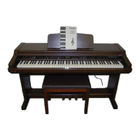
7.9. Removing the printed circuit boards
- Remove the keyboard cover (see step “Removing the keyboard
cover ”).
- Pull out the connectors on the printed circuit boards.
MAIN P.C.B.
1. Remove the MAIN P.C.B. mounting screws (A x 2 pcs., B x 3 pcs.).
2. Release the claws of the 3 P.C.B. holders.
AS P.C.B.
1. Release the claws of the 9 P.C.B. holders.
2. Remove the ground wire holding screws (C x 2 pcs.).
JACK P.C.B.
1. Remove the MAIN P.C.B..
2. Remove the JACK P.C.B. mounting screws (D x 4 pcs.).
3. Remove the ground wire holding screw (E x 3 pcs., F x 2 pcs.).
HP P.C.B.
1. Remove the keyboard assembly (see step “Removing the
keyboard assembly ”).
2. Remove the HP P.C.B. mounting screws (G x 2 pcs.)
3. Remove the headphone jack mounting nuts (H x 2 pcs.).
ACP P.C.B.
- Release the claws of the AC IN connector bracket.
7.10. Removing the Disk Drive unit
1. Remove the keyboard cover (see step “Removing the keyboard
cover ”).
2. Pull out the connector from the Disk Drive unit.
3. Remove the chassis on which Disk Drive unit is attached (I x 4
pcs.).
4. Remove the Disk Drive unit mounting screws (J x 4 pcs.).
13