B
Ref. DCD01/3067 - UC500_en_D
6/27
BDescription of the Control Unit
1. Description
The Control Unit is designed to manage the markings performed by the numerically controlled heads
manufactured by Technifor.
It contains the control and power electronics, as well as an LCD screen.
A keyboard of the type PS2 is connected to its front panel.
The Control Unit is supplied with:
• 1 bridged male SubD9 connector, for the reset function
• 2 feet + 2 truss head screws, so it can be installed on a workbench
• 2 plates + 4 countersunk head screws, for wall mounting
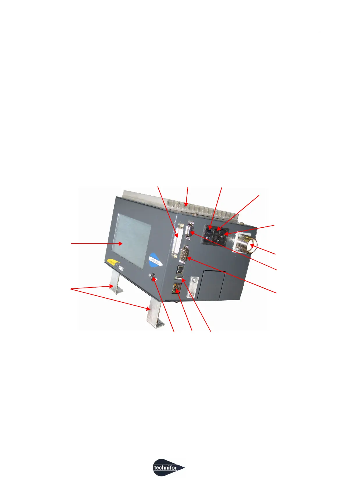
1 : LCD screen
2 : Two feet (delivered unassembled)
3 : MiniDin 6 point(s): PS2 keyboard
4 : RJ45: Ethernet connection
5 : USB A
6 : SubD 9M: RS232 management connection
7 : SubD 9F: dedicated Inputs/Outputs
8 : Head/CCU connecting cable
9 : Power cable
10 : Fuse
11 : On / Off switch
12 : Heat sink device
13 : SubD 25F: generic Inputs/Outputs
2
1
3
4
5
6
7
8
9
10
11
12
13