Do you have a question about the TechnipFMC Smith Meter 210 and is the answer not in the manual?
Check outside packing case for shipping damage. Inspect unit for damaged or missing parts upon receipt.
Ensure the valve is installed with the correct flow direction, indicated on the valve body.
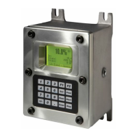
Wiring details are covered in the appropriate controller manual for AccuLoad and microLoad devices.
Explains the Smith Meter® Model 210 Valve's fundamental components and how solenoids control its operation.
Sequential steps recommended for initial system start-up to ensure stable and proper operation.
Provides a maintenance schedule for solenoids based on actuation counts and elastomer inspection guidelines.
Directs users to reference the valve parts list for recommended spare parts.
Lists the necessary tools for performing service and maintenance on the valve.
Explains that the document follows a sequential flow of actions with accompanying pictures.
Advises servicing the valve in a horizontal plane to prevent component misalignment.
Check outside packing case for shipping damage. Inspect unit for damaged or missing parts upon receipt.
Ensure the valve is installed with the correct flow direction, indicated on the valve body.
Wiring details are covered in the appropriate controller manual for AccuLoad and microLoad devices.
Explains the Smith Meter® Model 210 Valve's fundamental components and how solenoids control its operation.
Sequential steps recommended for initial system start-up to ensure stable and proper operation.
Provides a maintenance schedule for solenoids based on actuation counts and elastomer inspection guidelines.
Directs users to reference the valve parts list for recommended spare parts.
Lists the necessary tools for performing service and maintenance on the valve.
Explains that the document follows a sequential flow of actions with accompanying pictures.
Advises servicing the valve in a horizontal plane to prevent component misalignment.
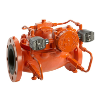
The Smith Meter® Model 210 Digital Electro-Hydraulic Set Stop is a hydraulically-operated, diaphragm-controlled valve designed for precise flow control, typically used in conjunction with an AccuLoad or microLoad controller in petroleum applications. Its primary function is to regulate flow rates and prevent line shock during loading operations.
The Model 210 valve fundamentally consists of a Smith Meter® 200 Series Valve with two solenoid controls: a normally open (N.O.) solenoid and a normally closed (N.C.) solenoid. A valve response control device, usually a needle valve, is positioned between each solenoid and its respective upstream or downstream port. This device allows for fine-tuning of the valve's opening and closing rates and provides control loop isolation for easier service. Adjustments to these devices control the flow rate to and from the cover chamber, enabling the valve to adapt to different product viscosities and pressures.
The operation is controlled by the solenoids. When both solenoids are energized, high upstream pressure is blocked from reaching the main valve cover, and the pressure in the cover vents downstream (lower pressure), causing the valve to open. Conversely, when both solenoids are de-energized, the downstream control loop is blocked, and high upstream pressure closes the valve.
During normal flow, the N.O. solenoid is energized while the N.C. solenoid is de-energized, trapping pressure in the cover and hydraulically locking the valve poppet in a fixed open position, thus maintaining a constant flow rate. If operating conditions change and alter the flow rate for a given valve opening, the flow controller (e.g., microLoad or AccuLoad) momentarily signals the appropriate solenoid to open or close, readjusting the valve's position and the flow rate to its set value.
When the set flow rate changes (e.g., from a low flow start to a high flow limit, or during a multi-step valve shutdown), the solenoids are signaled to adjust the flow rate to the new set value. When the delivered product reaches a predetermined (field-adjustable first stage trip) value in the controller, valve closure is initiated. The flow controller ramps down the flow in a multi-step manner to prevent line shock. A typical load cycle involves a low flow start, followed by a first high flow rate, then a second high flow rate, and finally a multi-stage shutdown initiated by first and final stage trip points.
| Brand | TechnipFMC |
|---|---|
| Model | Smith Meter 210 |
| Category | Control Unit |
| Language | English |