IST-2138.KM02.01/B Istruzione / User’s Manual / Manuel d’utilisation Pag.5/11
TECNOCONTROL S.r.l. Via Miglioli 47 SEGRATE ( MI ) Tel: 02/26 92 28 90 Fax: 02/21 33 734
Preheating: when powered, the sensor needs a time of preliminary heating of about 60 seconds. During this period
the yellow LED “FAULT” flashes. After this period, the yellow LED light off, the green LED “ON” illuminates to indicate
normal functioning. After this period the unit is able to detect gas even if it attains the optimum stability conditions
after about 24 hours continual functioning.
Normal operation: the green LED “ON” should be light on.
1st ALARM: when gas concentration attains 1st alarm level the 1st red LED (ALARM 1) illuminates and after about 12
seconds, the “ALARM 1" relay will activate.
2nd ALARM: when the Gas concentration attains 2nd alarm level the 2nd red LED (ALARM 2) illuminates and after
about 30 seconds, the “ALARM 2" relay will activate.
3rd ALARM: when the Gas concentration attains 3rd alarm level the 3rd Red LED (ALARM 3) illuminates and after
about 60 seconds, the “ALARM 3" relay will activate.
Faults: the yellow LED illuminates and the "S" output falls down to 0mA. (The different faults are listed below) and
the “FAULT” normally activated relay deactivate. The "FAULT" relay, if necessary, can be used both to signal remotely
an occurred damage and to signal the absence of power to the instrument.
Yellow LED illuminates each 4 seconds (with green LED activate): this happens when the “Cartridge Sensor” has
overcome its period of life (about 5 years) and its correct operation is not longer guaranteed. The detector keeps on
operating normally but it is necessary to replace, as soon as possible, the “Cartridge Sensor” with a new one. The type to
be required is listed on Page 1. The replacement procedure is described in the atta
ched manual.
Yellow LED activate, green LED off (FAULT relays activate and 0mA output signal): this signal different kind of faults.
1) The Dip Switch set up is wrong, please verify (see Table 2 and 3).
2) The “Cartridge Sensor” is not working, please replace with new one.
3) If a new “Cartridge” is installed or it is not correctly connected or a not compatible one is mounted. Please check the
“Cartridge“ connections and compatibility (see on page 1) these checks are made connecting and disconnecting the device. If
the condition does not change, please replace the unit and/or send it back to the supplier to repair.
Yellow and green LED activates (FAULT relays activate and 0mA output signal): this happens when the “Cartridge
Sensor” is not working. First try to perform the procedure of “ZERO” as described in the section “Test and Calibration >
Zero adjust” then disconnect and connect the unit, finally try to replace a new “Cartridge Sensor”. If the condition is not
change, please replace the unit and/or send it back to the supplier to repair.
All LED activate (FAULT relays activate and >24mA output signal): this happens when the “Cartridge Sensor” is not
working or gas concentration is out of scale (higher than 25% LEL) If there are not any gas leaks and the condition
is not change, please replace the unit and/or send it back to the supplier to repair.
INSTALLATION
The detector must be accurately installed and testing according to the national dispositions in force on the safety of
the plants and installation of electric devices in areas with danger of explosion.
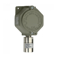
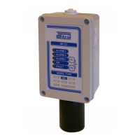
Mounting: The Fig. 2 shows the instrument size. The unit must be positioned vertically with the sensor downwards.
Models SE138KG should be fixed at 20-30 cm from the floor (LPG is heavier than air).
Models SE138KM should be fixed at 20-30 cm from the ceiling (Methane is lighter than air).
Models SE138KB should be fixed at 20-30 cm from the floor (Petrol vapours are heavier than air).
Models SE138KI should be fixed at 20-30 cm from the ceiling (Hydrogen is lighter than air).
Electrical Connection (see Fig.2): the maximum distance to install each detector from the power supply show in the
Table 1. If more than one detector is to be powered in parallel, it is necessary to consider the voltage drop across the
supply cable. Normally use a two wire cable (not shielded) for power supply + the conductors for output relay. If the
output signal is used in mA, please use 3 conductors screened cables + conductors for relay output. The max load re-
sistor is 50 ohm with 12Vdc (-10%) power supply, while is 500 ohm with 24Vdc (-10%) power supply (see fig.4).
Power Supply terminals, on the main board, are polarized plug-in type, it is necessary to extract them to make the con-
nection. The relays terminals, on outputs board, are fixed. The SSR relays are tension free SPST (Single Pole Single
Throw) contacts and should be set NO (Normally Open) or NC (Normally Closed) by positioning the 4th Dip-Switch (see
Table 3). With the Dip-Switches from 1 to 3 the concentration for alarm activations is determined.
Note: Dip-Switch should be set with instrument powered off (see Table 2). Using the unit with the Dip-
Switch in a reserved position, the fault indication will be activated (see "Operational description> Faults").
Important: Once installation is completed, power up the unit, wait about 1 to 2 hours and then to adjust the sensor
to the environment, only if it is necessary, carry out the ”Zero Adjust” (see ‘Test and Calibration).
WARNING
Average life: The sensitive element used in this detector has an excellent stability in time. In fresh air and in normal
working condition the sensor's life is about 5 years from the date of installation. After this period the yellow LED
“FAULT” flashes every 4 seconds, is necessary replacing the “Cartridge Sensor”.
Periodical testing: we advise to carry out working tests every 12 months. Tests, Zero Adjust and Calibration with
Gas/Air mixture as explained in chapter “Tests and Calibration”.
Note: the detector is not able to detect gas leaks occurring outside the room where it is installed, neither inside
walls nor under the floor.
Important: The catalytic Pellistor sensor operates only in presence of Oxygen. Do not use pure gases or a
lighter directly on the sensor since they could damage it irremediably.
Warning:
Consider that in polluted environments, or with vapours of flammable substances (including solvents),
the lifetime of the sensor can be reduced. Some substances cause a permanent reduction of sensitivity, avoid con-
 Loading...