Do you have a question about the technoswitch TEC247 and is the answer not in the manual?
How the fire control panel monitors zones and reacts to Fire or Fault conditions.
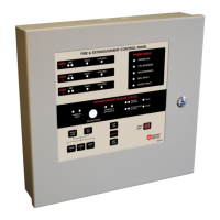
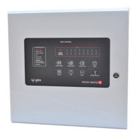
Details on system status, zone indications, and user functions.
Enclosure, keypad, detectors, sirens, beacons, and secondary equipment.
Description of the yellow surface mount Manual Call Point.
Diagrams for zone circuits, bell outputs, and control connections.
Routing and securing high voltage AC mains wiring into the enclosure.
Connecting two 12 V DC batteries in series for panel power and charging.
Supplying 27.5 V DC to the motherboard and AUX output.
Understanding LED indicators for power supply faults.
Details on AC Supply Fault, Common PSU Fault relays and 26 V DC Supply Fault output.
Procedures for resetting the panel's CPU and power supply.
Wiring and monitoring of detection zone circuits with EOL resistors.
Wiring requirements for manual call points in fire zones.
Connecting and monitoring bell circuits with Zener diodes for sounders.
Activating solenoids, detonators, and using common outputs.
Panel functions for manual/automatic release and call point wiring.
Safety door switch feature and setting the extinguishant release time delay.
Explanation of panel LEDs for Power On, CPU Running, Bell Fault, Maintenance, Supply Fault.
Using Reset, Silence, Evacuate, Lamp Test, Zone Isolate, and Walk-test functions.
Switching between manual and automatic modes for release activation.
LED indications for Release Initiated and Extinguishant Released.
Troubleshooting steps for persistent fire conditions preventing reset.
Troubleshooting steps for persistent fault conditions preventing reset.
Troubleshooting steps for bell circuit faults affecting operation.
Guidance on using EOL devices and Zener diodes for monitored outputs.
| Category | Control Panel |
|---|---|
| Contact Configuration | SPDT |
| Vibration Resistance | 10-55Hz, 1.5mm amplitude |
| Contact Material | Silver Alloy |
| Insulation Resistance | 100MΩ min |