TEC247 Fire & Extinguishant Control Panel – INSTALLATION & OPERATION MANUAL
DOC NO. PRMAN-0003 TEC247 Rev 04.12 191209.docx - 2 - E. &O.E.
1. SYSTEM DESCRIPTION
A number of fire detection devices are wired into zones. The fire control panel monitors the circuits of these
detection zones and will react on detecting either a Fire or a Fault condition within a zone.
In the case of a Fault condition (detector fault, short or open circuit fault) the panel’s internal buzzer will sound and
the respective zone’s FAULT LED on the facia will flash or remain on. The common fault relay on the motherboard
will also change state. This is under normal circumstances energised (fail safe) and thus will be de-energised on
Fault condition.
In the case of a Fire condition, the panel’s internal buzzer will sound and the respective zone’s FIRE LED will flash.
The bell output contacts on the motherboard will supply 24 V DC power. Three other standard outputs will also
operate. These outputs are the Common Fire Alarm output, the Fire Brigade output and the Zone Repeat relay.
Fire Zone 1 and Zone 2 are connected to the extinguishant release output. An alarm from both these zones will
initiate the discharge cycle if the control panel is in automatic mode. The panel may be switched to manual release
mode in order to de-activate the automatic extinguishing mode.
A yellow extinguishant release Manual Call Point (MCP) has been supplied with the panel. This may be wired to
the remote MCP contact of the control panel. A 680 resistor must be wired to this Manual Call Point (see 5.3
Manual Call Points on page 9).
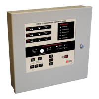
▪ System Status indications include Power On, CPU Running, Bell Fault, Maintenance Mode, Supply Fault.
▪ Zone indications include Fire Alarm, Fault and Isolate indications.
▪ Extinguishing Status indications include Initiate Release + Fault, Extinguishant Released + Fault, Manual
Only, and Auto & Manual.
User functions include Silence, Reset, Evacuate, Lamp test, Zone Isolate, and Walk-test (see 6 SYSTEM
OPERATION on page 11).
2. SYSTEM COMPONENTS
NB: Version 6 and above CPU and motherboards are not backward compatible with version 5 PCBs although
boxes, keypads and power supplies are common. You will find the version label on the CPU board and
motherboards.
▪ Enclosure with membrane keypad, auto/manual key switch, motherboard,
CPU board and Power supply board.
- CPU labelled – T247CPU (Product Code: PCB-TEC247-CPUx)
- Motherboard labelled – T247MB (Product Code: PCB-TEC247-MBx)
- Power Supply – PCB-PSU2A
Ionisation or optical smoke detectors, heat detectors and manual call points.
Specialised equipment such as linear heat detection, optical beam detectors,
aspirating smoke detectors, and UV/IR flame detectors may be used -
modifications to the connections may apply with these.
Extinguishant interface, repeater panels, mimic panels, GPRS communicators,
telediallers, relays and/or transmitters may be connected.
Some of these may need additional interface boards.