TEC247 Fire & Extinguishant Control Panel – INSTALLATION & OPERATION MANUAL
DOC NO. PRMAN-0003 TEC247 Rev 04.12 191209.docx - 10 - E. &O.E.
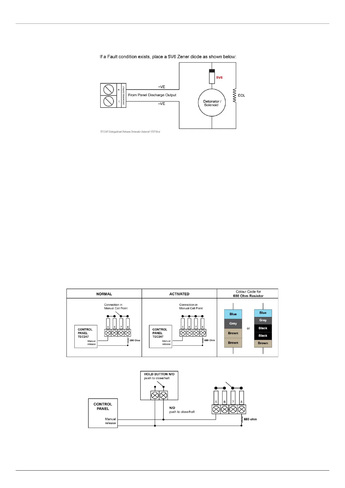
5.5 EXTINGUISHANT RELEASE DETONATOR/SOLENOID
The discharge output provides 24 V DC 1 Amp output to activate solenoids and detonators. The duration of this
output being active can be set on P12, 5 seconds or 5 minutes.
FIGURE 13 EXTINGUISHANT RELEASE DETONATOR/SOLENOID
5.6 COMMON OUTPUTS
The two outputs labelled FBC are a voltage reversal output. This circuit will reverse voltage polarity on a common
Fire Alarm condition. Resetting the panel will restore the original polarity.
The Fire and Fault contacts are potential free change over contacts. The fault contact is under Normal condition
energised (fail safe). If mains power is removed from the panel, the fault contact will, after 30 seconds de-energise
and thus change state.
A potential free change over contact is supplied per zone. A Fire Alarm condition will activate these relay contacts.
All potentially free relay outputs are rated to switch 30 V DC 1 Amp (non-inductive).
5.7 EXTINGUISHANT CONTROL
This control panel also operates as a lock off unit and is used to control the release of an extinguishant system
between manual and automatic release.
Manual release of the extinguishant is achieved by lifting the protector flap and breaking the glass on the
“Extinguishant Release” call point supplied with the panel. A “Discharge Hold” button may be installed to allow a
temporary or permanent halt to the discharge signal.
5.8 MANUAL EXTINGUISHANT RELEASE CALL POINT (ON REMOTE MCP CONTACTS)
The Manual Extinguishant Release Call Point must be wired as follows:
▪ A Discharge Hold Button may be installed:
FIGURE 14 MANUAL RELEASE AND HOLD CIRCUITS
The automatic release of the extinguishant requires two separate fire alarm signals from Fire Zone 1 and Fire Zone