TD20 Series VFD Function Parameters
-38-
Detailed instruction of parameters
Speed loop
proportional
gain1
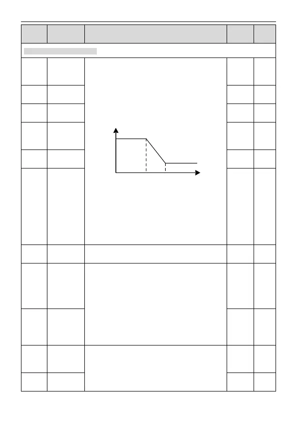
The parameters P03.00–P03.05 only apply to vector
control mode. Below the switching frequency 1 (P03.02),
the speed loop PI parameters are: P03.00 and P03.01.
Above the switching frequency 2 (P03.05), the speed
loop PI parameters are: P03.03 and P03.04. PI
parameters are gained according to the linear change of
two groups of parameters. It is shown as below:
Output frequency
PI parameters
P03.00, P03.01
P03.03, P03.04
P03.02 P03.05
PI has a close relationship with the inertia of the system.
Adjust on the base of PI according to different loads to
meet various demands.
The setting range of P03.00 and P03.03: 0–200.0
The setting range of P03.01 and P03.04: 0.000–10.000s
The setting range of P03.02: 0.00Hz–P00.05
The setting range of P03.05: P03.02–P00.03
Speed loop
integral time1
Speed loop
proportional
gain 2
Speed loop
integral time 2
0–8 (corresponds to 0–2
8
/10ms)
Compensation
coefficient of
vector control
electromotion
slip
Slip compensation coefficient is used to adjust the slip
frequency of the vector control and improve the speed
control accuracy of the system. Adjusting the parameter
properly can control the speed steady-state error.
Setting range: 50%–200%
Compensation
coefficient of
vector control
brake slip
Current loop
percentage
coefficient P
Note:
These two parameters adjust the PI adjustment
parameter of the current loop which affects the dynamic
response speed and control accuracy directly.
Generally, users do not need to change the default