TD20 Series VFD Installation Guide
-16-
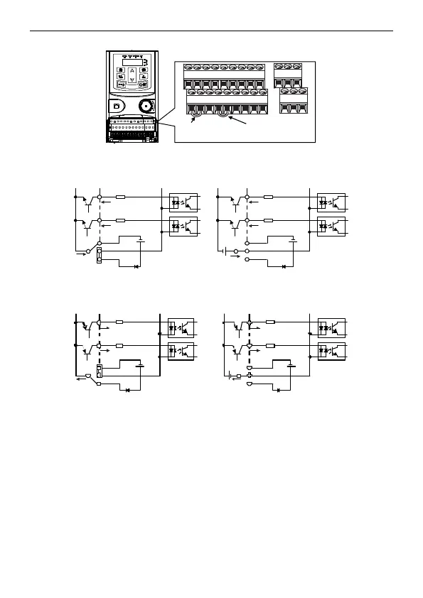
supply. The default setting is NPN internal mode.
U-shaped contact
tag between
+24V and PW
U-shaped contact
tag between
COM and CME
Figure 3-8 U-shaped contact tag
If the signal is from NPN transistor, please set the U-shaped contact tag between +24V and PW as
below according to the used power supply.
S1
S2
COM
PW
+ 24V
COM
+24V
S1
S2
COM
PW
+ 24V
COM
+24V
+ 24V
Figure 3-9 NPN modes
If the signal is from PNP transistor, please set the U-shaped contact tag as below according to the used
power supply.
S1
S2
COM
PW
+24V
COM
+24V
S1
S2
COM
PW
+24V
COM
+24V
Figure 3-10 PNP modes
3.3 Layout protection
3.3.1 Protecting the VFD and input power cable in short-circuit situations
Protect the VFD and input power cable in short circuit situations and against thermal overload.
Arrange the protection according to the following guide.
 Loading...

