TD20 Series VFD Product Overview
-5-
additional protection to VFDs.
2.1.4 Installation confirmation
Check as follows after the installation:
1. Check that the load range of the input and output cables meet the need of actual load.
2. Check that the accessories of the VFD are correctly and properly installed. The installation cables
should meet the needs of every component (including reactors, input filters, output reactors, output
filters, DC reactors, braking units and braking resistors).
3. Check that the VFD is installed on non-flammable materials and the calorific accessories (reactors
and brake resistors) are away from flammable materials.
4. Check that all control cables and power cables are run separately and the routation complies with
EMC requirement.
5. Check that all grounding systems are properly grounded according to the requirements of the VFD.
6. Check that the free space during installation is sufficient according to the instructions in user's
manual.
7. Check that the installation conforms to the instructions in user's manual. The VFD must be
installed in an upright position.
8. Check that the external connection terminals are tightly fastened and the torque is appropriate.
9. Check that there are no screws, cables and other conductive items left in the VFD. If not, get them
out.
2.1.5 Basic commissioning
Complete the basic commissioning as follows before actual utilization:
1. Autotune. If possible, de-coupled from the motor load to start dynamic autotune. Or if not, static
autotune is available.
2. Adjust the ACC/DEC time according to the actual running of the load.
3. Commission the device via jogging and check that the rotation direction is as required. If not,
change the rotation direction by changing the wiring of motor.
4. Set all control parameters and then operate.
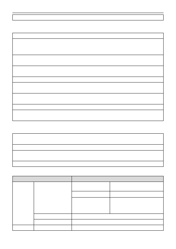
2.2 Product specification
Allowable voltage fluctuation
AC 1PH 200V–240V
AC 3PH 200V–240V
AC 3PH 380V–480V
50Hz or 60Hz Allowed range: 47–63Hz