TD20 Series VFD Installation Guide
-15-
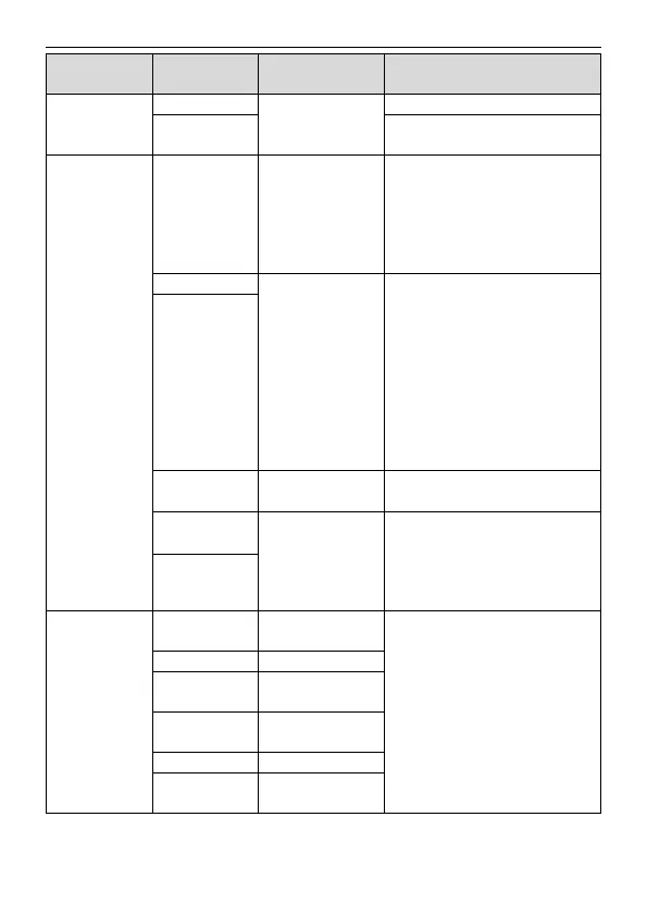
Contact capacity: 50mA/30V
Common terminal of the open
collector output
External 10V
reference power
supply
10V reference power supply
Max. output current: 50mA
As the adjusting power supply of the
external potentiometer
Potentiometer resistance: 5kΩ
above
1. Input range: AI2 voltage and
current can be chosen:
0–10V/0–20mA; AI3: -10V–+10V.
2. Input impedance:voltage input:
20kΩ; current input: 500Ω.
3.Voltage or current input can be
set by dip switch.
4. Resolution: the minimum AI2/AI3
is 10mV/20mV when 10V
corresponds to 60Hz.
1. Output range: 0–10V or 0–20mA
2. The voltage or the current output
is depended on the dip switch.
3. Deviation±1%, 25°C when full
range.
RO1 relay output, RO1A NO, RO1B
NC, RO1C common terminal
RO2 relay output, RO2A NO, RO2B
NC, RO2C common terminal
Contact capacity: 3A/AC250V
3.2.6 Input/Output signal connection figure
Please use U-shaped contact tag to set NPN mode or PNP mode and the internal or external power
 Loading...

