TD20 Series VFD Installation Guide
-14-
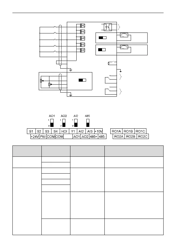
3.2.4 Wiring diagram of control circuit
Multi-function input terminal 1
Multi-function input terminal 2
Multi-function input terminal 4
High speed pulse input collector
Multi-function input terminal 3
Open collector input optional
Y1 output
Analog output
Analog output
Relay 1 output
Relay 2 output
S1
S2
S3
S4
HDI
COM
PW
+24V
PE
+10V
AI2
AI3
PE
GND
AI2
V I
Y1
COM
AO1
AO2
V I
V
I
AO1
AO2
0–10V/0–20mA
0–10V/0–20mA
COM
COM
485
485+
485-
RO1A
RO1B
RO1C
RO2A
RO2B
RO2C
Figure 3-6 Wiring of control circuit
3.2.5 Terminals of control circuit
Figure 3-7 Terminals of control circuit
485 communication interface
1. Internal impedance: 3.3kΩ
2. 12–30V voltage input is available
3. The terminal is the dual-direction
input terminal
4. Max. input frequency: 1kHz
High frequency
input channel
Except for S1–S4, this terminal can
be used as high frequency input
channel.
Max. inputfrequency: 50kHz
Duty cycle: 30%–70%
To provide the external digital power
supply
Voltage range: 12–30V
 Loading...

