TD20 Series VFD Function Parameters
-70-
Detailed instruction of parameters
This parameter means the sampling cycle of the
feedback. The modulator calculates in each sampling
cycle. The longer the sapling cycle is, the slower the
response is.
Setting range: 0.001–10.000s
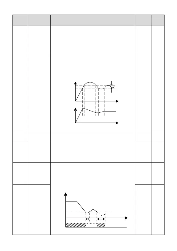
PID control
deviation limit
The output of PID system is relative to the maximum
deviation of the close loop reference. As shown in the
diagram below, PID adjustor stops to work during the
deviation limit. Set the function properly to adjust the
accuracy and stability of the system.
Output frequency
T
T
Feedback value
Bias limit
Reference
value
Setting range: 0.0–100.0%
Output upper
limit of PID
These parameters are used to set the upper and lower
limit of the PID adjustor output.
100.0 % corresponds to Max. Frequency or the Max.
Voltage of ( P04.31)
Setting range of P09.09: P09.10–100.0%
Setting range of P09.10: -100.0%–P09.09
Output lower
limit of PID
Feedback
offline
detection
value
Set the PID feedback offline detection value, when the
detection value is smaller than or equal to the feedback
offline detection value, and the lasting time exceeds the
set value in P09.12, the VFD will report "PID feedback
offline fault" and the keypad will display PIDE.
T
Output frequency
t1
t2
P09.11
t1<t2, so the VFD
continues to work
t2=P09.12
In running
Fault output PIDE
PIDE
Setting range of P09.11: 0.0–100.0%
Feedback
offline
detection time