PROVASET T3LPF REV.20210610
53
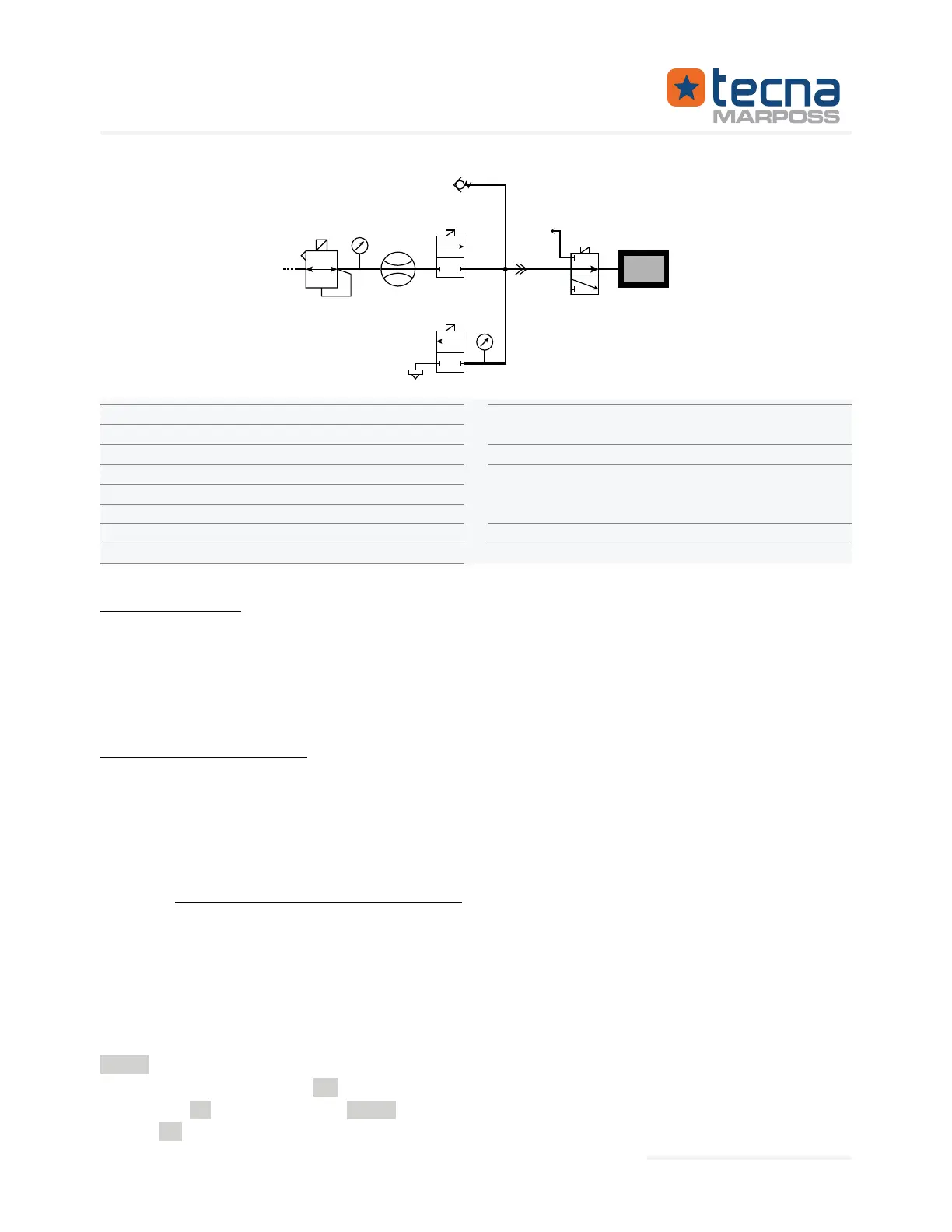
RPv Test pressure regulator
Pv Regulated pressure
Flow sensor
V1 In
ternal valve
V2 Internal valve
PR Test pressure
S Discharge connection
Mas
ter leak connection
TEST Output connection to the test cir-
cuit
V3 External valve
J Co
mponent being tested or in test
chamber (bell) with the component
being tested inside
Test volume
RPv
Pv
SF
V1
V2
PR
FC
Staubli RBE03
V3
S
J
TEST
Vp
Volume control:
•
measurements P1 and P2, corresponds to the programmed RVP% parameter,
within the permitted tolerance limit (+/- RVP%MAX), the test cycle proceeds to
the leak measurement phase T3, otherwise the test ends with a FAILED result,
due to RVP% error.
T3: measure test phase
• The leak measurement phase is performed in the same way as the basic leak
test cycle;
• the sealing is checked on the total volume, from valve V1 to the test volume;
• if the test is limited to the volume control, the measurement phase T3 can be
avoided by programming the parameter T3=0.
5.7.2 Volume+leak test: test parameters
The volume+leak test uses the same parameters as the leak test, adding the param-
eters for the volume control.
RVP%
circuit; range 100.0: 649.99 %.
RVP%
Example:
PR = 1000 mbar, RVP%
phase
P=1000*(140.00/100)=1400 mbar.
Represented By: GTEK AUTOMATION Lake Forest, CA 92630 Ph. 949-680-4242 www.gtek-automation.com
 Loading...