56 EN - Operator’s manual
Place the control desk in the position provided for.
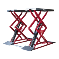
Assemble the foot-protection bars (A) and the ramps (B), using the relevant screws (Fig. 7a)
7
7a
The lift must be fastened to the ground.
The following is necessary to anchor the machine to the oor:
1 Percussion drill for concrete with 12 mm bit.
2 8 FISCHER FH II 12/50 H heavy duty dowels (or equivalent product from other
manufacturer).
3 Torque wrench with maximum setting at least 22,5 Nm.
Also ensure that the strength of the concrete is at least 250 Kg/cm
2
up to a depth of
130 mm.
Proceed as follows:
1 Drill with 12 mm bit to a depth of 130 mm.
2 Clean the hole.
3 Push the dowels into the hole, tapping gently with a hammer.
4 Tighten the bolts with a torque wrench set to 22,5 Nm (if this value cannot be ob-
tained, the hole is too large or the concrete is not sufciently solid).
weight of the equipment plus the maximum load allowed. The
must also be taken into account.
Any damage deriving from failure to follow the instructions given
above cannot be charged to the manufacturer and may cause
the warranty to become null and void.
7.6 Hydraulic system connection
To connect the hydraulic unit to the pipes coming from the hydraulic cylinders, it is neces-
sary to remove the front casing of the hydraulic unit and remove the screwed in plugs both
on the ends of the hydraulic pipes as well as on the T union located on the hydraulic unit.
Once the plugs are removed, connect the pipes to the respective unions.