EasyManua.ls Logo

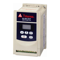
TECO T-Verter E2-403-H3F - User Manual

TECO T-Verter E2-403-H3F
64 pages
To Next Page IconTo Next Page
Loading...
E2 Adjustable Speed Driver
Microprocessor Controlled
IGBT Drive
Inverter Motor Speed Regulator
Operating Manual
High Performance Adjustable Speed Micro Drives
E2 Series
110V
0.2~0.75KW
( 0.53~1.6KVA )
220V
0.2~2.2KW
( 0.53~4.0KVA )
440V
0.75~2.2KW
( 1.7~4.0KVA )

Table of Contents

Question and Answer IconNeed help?

Do you have a question about the TECO T-Verter E2-403-H3F and is the answer not in the manual?

TECO T-Verter E2-403-H3F Specifications

General IconGeneral
BrandTECO
ModelT-Verter E2-403-H3F
CategoryDC Drives
LanguageEnglish

Summary

Preface and Safety Symbols

General Safety Precautions

Highlights critical safety warnings like electric shock hazards and grounding requirements.

Chapter 1 Safety Precautions

Operation Precautions: Before Power Up

Essential safety steps before applying power, including wiring and installation safety.

Operation Safety: Power Applied

Precautions When Power is Applied

Advises against connecting/disconnecting while powered and details momentary power loss handling.

Operational Safety Guidelines

Precautions During Motor Operation

Safety measures for connecting/disconnecting motors and handling heat-generating components.

Chapter 2 Hardware Installation

Installation Site Requirements

Detailed site requirements including temperature, humidity, ventilation, and mounting.

Functional Specifications

Wiring and Peripheral Specifications

EMI Connections and Mounting

Wiring Diagram and Terminals

Primary and Control Circuit Wiring

Illustrates the main power and control circuit connections to the inverter terminals.

Terminal Descriptions

Primary Circuitry Terminal Block (TM1)

Details the function of each terminal in the primary circuitry block.

Control Circuitry Terminal Block (TM2)

Explains the function of each terminal in the control circuitry block.

Installation for N4 X (IP65) Type

Connections and EMC Mounting (Without Switch)

Connections and EMC Mounting (With Switch)

Installation for E2-202-403 N4 X (IP65) Type

Connections and EMC Mounting (N4 S Switch Type)

Connections and EMC Mounting (N4 Without Switch)

Chapter 3 Software Operations

Keypad Operation Instructions

Explains how to use the inverter's keypad for operation and parameter setting.

Parameter List

Parameter Functions and Settings

Lists all available parameters, their functions, ranges, and factory settings.

Parameter Function Descriptions (F_00-F_09)

Factory Adjustment and Time Settings

Details F_00, F_01 (Accel. Time), and F_02 (Decel. Time) including calculation formulas.

Operation Mode and Direction Settings

V;F Pattern Settings

Frequency and Control Settings

Speed Control and Carrier Frequency

Stopping and Braking Functions

Motor Protection Features

Electronic Thermal Overload Protection

Describes motor and inverter thermal protection settings and behavior.

Multifunction Input Terminals

Input Terminal Functions (F_19, F_20)

Details functions for multifunctional input terminals like JOG, multi-speed, and emergency stop.

Multi-function Output and Lock-out

Auto-Restart and Fault Handling

Momentary Power Loss Auto-Restart (F_23)

Details auto-restart behavior after momentary power loss.

Factory Settings and Special Functions

Malfunction Indications and Countermeasures

Manual Reset Inoperative Malfunctions

Lists malfunctions that do not reset manually and their causes/solutions.

Auto-Reset Malfunctions

Lists malfunctions that may auto-reset and their causes/solutions.

Operative Malfunction Troubleshooting

Transient Over-Current Malfunctions

Addresses issues like OCS, OCA, OCC, OCd, OCb, and their remedies.

Over-Voltage and Heat Malfunctions

Covers OVC, LVC, OHC errors and their respective causes and countermeasures.

General Malfunction Examination

Motor Inoperative and Speed Issues

Provides checks for motor inoperability, incorrect direction, fixed speed, and speed variations.

Chapter 4 Troubleshooting

Inverter Malfunction Troubleshooting Flowchart

A flowchart to diagnose inverter malfunctions based on indications and checks.

Troubleshooting OC.OL Errors

OC.OL Malfunction Diagnosis

Step-by-step guide for handling OC.OL errors, checking PCB, detector, and voltage outputs.

Troubleshooting OV.LV Errors

OV.LV Malfunction Diagnosis

Step-by-step guide for handling OV.LV errors, checking appearance, voltage, and current.

Troubleshooting Motor Inoperability

Checking Motor Power and Wiring

Steps to diagnose motor inoperability by checking circuit breaker, voltage, and wiring.

Troubleshooting Motor Overheating

Diagnosing Motor Overheating Causes

Identifies causes of motor overheating like overloading, long operation, or cooling issues.

Troubleshooting Disturbing Motor Operation

Routine and Periodical Maintenance

Maintenance and Examination Procedures

Related product manuals