17
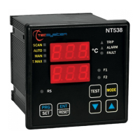
NT538
TEMPERATURE SENSOR DIAGNOSTICS
In case of failure or exceeded full scale value of one of the thermometric sensors installed on the machine to protect, the
FAULT relay opens immediately with the relative warning of faulty sensor on the corresponding channel (PT err).
Fcc indicates sensor short-circuited or minimum full scale value of the control unit exceeded -8°C (version 0°÷240°C)
and -48°C (version -40°C÷200°C)
Foc indicates sensor interrupted or maximum full scale value of the control unit exceeded 243°C (version 0°÷240°C)
and 203°C (version -40°C÷200°C)
To eliminate the message and reset the opening of the Fault contact, it is necessary to check the Pt100 connections and
replace the faulty sensor (if any). If the minimum/maximum full scale value has been reached, check that the ambient
conditions match the control unit reading.
Note: exceeding the minimum/maximum full scale value can also be caused by interference on the sensor lines; in this
case we recommend that you check:
the correct installation of the sensors and above all of the extension cable (as stated in the paragraph MEASUREMENT
SIGNAL TRANSFER)
the activation of: VOTING (see below) or FCD (see page 28) must always be operated taking into account the system
working conditions.
CAL message display: it appears when damage is found in the measurement circuit. The temperature values displayed
might be incorrect. Return the control unit to TECSYSTEM for repairs.
VOTING FUNCTION
The voting function is derived from the concept of redundancy which consists of the duplication of components of a system
with the intention of increasing reliability.
How the VOTING works?
Taking advantage of the principle indicated we use the probes installed to monitor the operation of the electrical machine,
but at the same time ensure the proper functioning of the probes themselves, discriminating any false alarms (generated
by installation errors or failures).
Enabling VOTING can be done by choosing one of three modes of selection "1-2-3" the control unit performs a
comparison of the temperature values measured on the channels monitored, enables switching of the tripping contact
(TRIP) only if it is found the overcoming of the TRIP threshold on at least two channels in the same period T.
Selecting VOTING "NO" function will be disabled.
In the tables, the selection, indicated below you will find the combination of channels with voting active available. For
greater flexibility in two combination we expected channel with voting enabled and others with voting disabled.
• Voting enabled: The contact TRIP switches only if at least two channels exceeded TRIP threshold.
• Voting disabled: The contact switches when the TRIP single-channel exceeds the threshold of TRIP
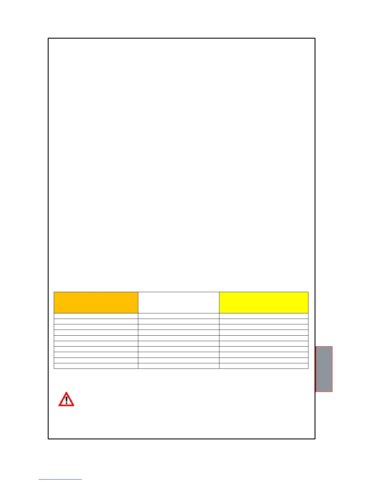
Selection 1
Selection 2
Selection 3
VOTING ENABLE CH1…..CH3 VOTING ENABLE CH1 …. CH6 VOTING ENABLE CH1 …. CH8
1 1 1
2 2 2
3 3 3
VOTING DISABLE CH4..CH8 4 4
4 5 5
5 6 6
6 VOTING DISABLE CH7..CH8 7
7 7 8
8 8
Note: The switching of ALARM signal still exceeded the threshold of alarm on each channel.
To enable Voting read the programming section on pages 14-15.
Attention: To control the transformer correctly from a temperature point of view, enabling the VOTING
function is allowed where the load distributed between the phases of the transformer is adequately
balanced. In addition, any conditions of FAULT: FCC-FCC-FCD on two or more channels, with active
voting, can determine the TRIP contact inhibition.