EasyManua.ls Logo

TECSYSTEM NT538 User Manual

TECSYSTEM NT538
30 pages
To Next Page IconTo Next Page
Page #1 background imageLoading...
Page #1 background image
1MN0123 REV. 0
operates with ISO9001 certified quality system
http://www.tecsystem.it
R. 1.3 23/05/16
“Translations of the original instructions”
ENGLISH
TECSYSTEM S.r.l.
20094 Corsico (MI)
Tel.: +39-024581861
Fax: +39-0248600783
NT538
INSTRUCTION MANUAL
Question and Answer IconNeed help?

Do you have a question about the TECSYSTEM NT538 and is the answer not in the manual?

TECSYSTEM NT538 Specifications

General IconGeneral
BrandTECSYSTEM
ModelNT538
CategoryControl Unit
LanguageEnglish

Summary

SAFETY REQUIREMENTS

QUALIFIED PERSONNEL OPERATION

Emphasizes that only qualified personnel should operate the device.

REPAIRS AND WARRANTY VOIDANCE

Instructions regarding opening the unit and warranty voidance.

TECHNICAL SPECIFICATIONS

TECHNICAL TESTS AND PERFORMANCE

Compliance, protection, dielectric strength, accuracy, and operating conditions.

DISPLAY AND DATA MANAGEMENT

OPERATIONAL AND DATA MANAGEMENT FUNCTIONS

Key operational modes and programming features of the unit.

FRONT PANEL

FRONT PANEL CONTROL KEYS AND BUTTONS

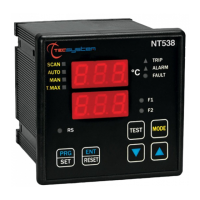
Describes the function of each key and button for operation and programming.

DISPLAY MODES AND TESTS

LED AND RELAY TESTING PROCEDURES

Procedure for testing the unit's indicator LEDs and relays.

ELECTRICAL CONNECTIONS

PT100 SENSOR AND POWER CONNECTIONS

How to connect Pt100 sensors and the power supply to the unit.

ELECTRICAL CONNECTIONS (AD)

POWER SUPPLY SPECIFICATIONS

POWER SUPPLY DETAILS AND PROTECTION

Details on universal power supply, voltage, grounding, and protection.

ALARMS AND VENTILATION

PROGRAMMING

CHANNEL ACTIVATION AND THRESHOLD SETTING

Steps for activating channels and setting alarm/trip thresholds.

PROGRAMMING FEATURES

TEMPERATURE SENSORS

PT100 SENSOR WIRING AND CONFIGURATION

Details on Pt100 sensor wiring and independent channel programming.

MEASUREMENT SIGNAL TRANSFER

MEASUREMENT SIGNAL TRANSFER CABLE REQUIREMENTS

Specifies cable types, sections, screening, and routing for Pt100 signals.

TEMPERATURE SENSOR DIAGNOSTICS

SENSOR FAULT DETECTION (FCC, FOC)

Explains FCC and FOC error codes for sensor issues.

VOTING FUNCTION

PROGRAMMED DATA DIAGNOSTICS

TEMPERATURE DIAGNOSTICS

COOLING FAN CONTROL

RS485 MODBUS OUTPUT

RS485 MODBUS: MODULE INTRODUCTION AND OPERATION

Overview of the Modbus module and operational notes for NT538 AD.

FUNCTION CODE

REMOTE PROGRAMMING NOTES

MODBUS ERROR CODES

MODBUS ERROR CODE CLASSIFICATION

Lists common Modbus error codes like unsupported function, wrong data address, and wrong data.

ILLEGAL DATA AND POLLING

ILLEGAL DATA ERROR CODES

Details specific programming errors and their corresponding error codes.

MODBUS MAPPING TABLE: HEADER

MODBUS MAPPING TABLE: HEADER INFO AND COMMANDS

Table mapping Modbus addresses to device information and commands.

MODBUS MAPPING TABLE: SYSTEM SETTING AND STATUS REGISTERS

Table mapping addresses for system settings and status monitoring.

MODBUS MAPPING TABLE: CONFIGURATION

MODBUS MAPPING TABLE: ADDRESS CONFIGURATION REGISTERS

Table for Modbus address, baud rate, and parity bit configuration.

MODBUS MAPPING TABLE: TEMPERATURE FAN SETTING REGISTERS

Mapping of Modbus addresses for fan ON/OFF settings and temperature ranges.

MODBUS MAPPING TABLE: CH3-CH8

MODBUS MAPPING TABLE: TEMP SETTINGS CH3-CH4

Modbus registers for temperature settings and alarm/trip points for channels 3 and 4.

MODBUS MAPPING TABLE: TEMP SETTINGS CH5-CH6

Modbus registers for temperature settings and alarm/trip points for channels 5 and 6.

MODBUS MAPPING TABLE: TEMP SETTINGS CH7-CH8

Modbus registers for temperature settings and alarm/trip points for channels 7 and 8.

MODBUS MAPPING TABLE: CH1-CH8

MODBUS MAPPING TABLE: CHANNEL SETTING REGISTERS CH1-CH8

Mapping Modbus addresses for channel settings configuration.

MODBUS MAPPING TABLE: CHANNEL STATUS REGISTERS CH1-CH8

Mapping Modbus addresses for reading channel status history.

FAIL SAFE FUNCTION

OUTPUT 4.20mA

4.20MA OUTPUT CAPABILITIES

Details on connecting devices, load impedance, and signal accuracy.

Pt100 EXTENSION CABLE SPECIFICATIONS

FCD FUNCTION

TROUBLESHOOTING

TROUBLESHOOTING: UNIT POWER AND FAULT ISSUES

Troubleshooting steps for power-on problems and specific fault messages.

TROUBLESHOOTING: SENSOR AND DISPLAY ISSUES

Solutions for sensor-related faults, incorrect readings, and tripping issues.

Related product manuals