4
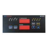
NT579-NT579 RS485
TECSYSTEM SHANGHAI
2) MOUNTING OF NT579 MONITORING DEVICE
Make a hole in the panel sheet with dimensions 152 x 76 mm.
Firmly tighten the device with the enclosed fixing kit.
3) SUPPLY OF NT579 CONTROL DEVICE
NT579 has a power supply of 18~36Vdc 50-60 Hz
When the monitoring device is directly fed from secondary winding of the
transformer to be protected, it can be damaged by high-intensity overvolt-
ages.
These problems occur if the main switch is connected without load.
Above mentioned problems are much more evident when the voltage 24
Vac voltage is directly taken from the transformer secondary bars and there
is a fixed capacitor battery to phase the transformer itself.
In case you have to replace an existing monitoring unit with a new
one, in order to guarantee its safe and correct working, you must re-
place the sensor/relay/supply connection terminals with the new ter-
minals supplied, provided that they are of a brand different from the
previously mounted ones.
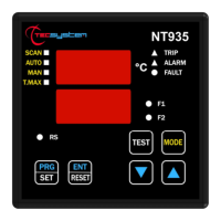
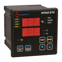
4) ELECTRICAL CONNECTIONS FOR ALARMS AND E VENTILATION
(FIGURE 2 PAGE 19)
Carry out the electrical connections on the removable rear terminals, after
having removed them from the meter.
All relays switch in OFF (as the unit turned off) and does not run any tem-
perature control when you enter one of the following modes: display pro-
gramming Vis, PRG programming, relay test
ALARM and TRIP relays switch only when the set temperature limits are ex-
ceeded.
FAULT relay (Fault) switches when the meter is fed, while gets de-
energised and when:
data memory fault (Ech message)
measuring circuit broken (CAL message)
a fault occurs to Pt100 sensors (Fcc, Fcc or Fcd)
supply voltage is lacking
during the power on reset after the data programming of the unit (local
or via modbus) or after the exit from visualizing program mode.
FAN output can be used to switch ON/OFF the cooling fans of the trans-
former by setting the unit program (table N. 20 at page 10, steps from 6 to
11)