The NT935-4 is a temperature protection control unit designed for monitoring and managing temperatures in various applications, particularly transformers. It offers a comprehensive set of features for temperature measurement, alarm management, fan control, and communication, ensuring the safe and efficient operation of the monitored system.
Function Description
The primary function of the NT935-4 is to monitor temperatures using Pt100 RTD sensors. It supports up to four sensor inputs, allowing for multi-point temperature surveillance. The device continuously displays temperatures and provides visual indications of alarm and fault conditions through dedicated LEDs.
A key aspect of the NT935-4 is its robust alarm management system. It features two alarm relays (ALARM and TRIP) that activate when predefined temperature thresholds are exceeded. These relays can be configured for either normally open (NO) or normally closed (NC) operation, offering flexibility in system integration. Additionally, a dedicated FAULT relay indicates sensor or operating failures, enhancing system reliability.
The unit also incorporates a cooling fan control function, allowing it to manage up to two fans (FAN1 and FAN2) based on temperature thresholds. This helps in maintaining optimal operating temperatures and preventing overheating. The fan control can be configured per channel, enabling tailored cooling strategies.
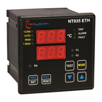
For advanced monitoring and control, the NT935-4 AD version includes Modbus RTU RS485 output and an optically isolated 4-20mA output. The Modbus interface allows for remote data acquisition and programming, integrating the unit into larger control systems. The 4-20mA output provides an analog signal proportional to the temperature, suitable for external display or recording devices.
The device features a "Fail Safe" function, which ensures that in the event of a power failure or internal fault, the relays revert to a safe state, preventing unintended operations. This function can be enabled or disabled based on specific application requirements.
An innovative "FCD Function" (Fast Change Detection) is also available, which analyzes the rate of temperature increase (°C/sec). This feature helps in identifying rapid temperature changes due to sensor faults, induced interferences, or specific operational issues like a blocked motor rotor, inhibiting false alarms and providing early warnings.
The "Voting Function" enhances reliability by comparing temperature values from multiple sensors. When activated, the TRIP contact will only switch if the TRIP threshold is exceeded on at least two channels over a specified period, reducing the likelihood of false trips caused by a single faulty sensor or localized anomaly.
Usage Features
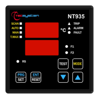
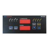
The NT935-4 offers a user-friendly interface with a 3-digit display for temperature and channel information, complemented by LEDs for status indication (SCAN, AUTO, MAN, T.MAX, ALARM, TRIP, FAULT, FAN1, FAN2).
Users can select different display modes:
- SCAN: Automatically cycles through all active channels, displaying their temperatures every 2 seconds.
- AUTO: Displays the temperature of the hottest channel.
- MAN: Allows manual selection of channels using up/down keys to view individual temperatures.
- T.MAX: Shows the maximum temperature reached by each sensor since the last reset, along with any alarm or fault conditions.
Programming the unit is straightforward, accessed via the PRG key. The programming menu allows users to set alarm and trip thresholds, configure fan control parameters, enable or disable channels, and adjust communication settings (for AD version). The system includes safeguards such as automatic exit from programming after inactivity and warnings for incorrect programming.
The device supports a "LED Test" function to verify the functionality of all display LEDs and an "Alarm Relay Test" to check relay operation without external devices. These tests contribute to easy maintenance and troubleshooting.
Alarm signals can be silenced using the RESET key, which causes the ALARM LED to flash until the temperature drops below the alarm threshold.
For the AD version, remote programming is possible via Modbus, allowing for configuration changes from a central control system. The Modbus mapping table provides detailed information on accessible registers for reading and writing data.
Maintenance Features
The NT935-4 is designed for durability and ease of maintenance. It features a self-diagnostic circuit that helps identify internal issues, such as EEPROM memory damage ("Ech Err") or measurement circuit faults ("CAL Err"). In such cases, the unit provides clear messages, guiding users to contact technical service if necessary.
Sensor diagnostics (Fcc, Foc, Fcd) are integrated to detect short-circuited, interrupted, or rapidly increasing temperature sensors, providing immediate warnings and activating the FAULT relay. This helps in quickly identifying and addressing sensor-related problems.
The unit's design includes protection against electromagnetic interference and a robust housing, contributing to its longevity in industrial environments. Removable terminal strips simplify wiring and replacement.
For optimal performance and to prevent reading anomalies, the manual provides detailed instructions on proper sensor installation and cabling, including recommendations for cable type, screening, and routing. Adherence to these guidelines is crucial for accurate temperature measurement and reliable operation.
The "Fan Test" function allows for periodic activation of cooling fans for a set duration, regardless of temperature, ensuring that the fans and their control apparatus are functioning correctly. This proactive maintenance feature helps prevent cooling system failures.
In case of persistent problems or complex issues, the manual directs users to contact TECSYSTEM's technical department, providing contact information for support. The device also comes with a warranty, subject to proper installation and use as outlined in the manual. Information on equipment disposal is also provided, aligning with environmental regulations.