POWER SUPPLY
The NT935-4 control unit has UNIVERSAL power supply, i.e. it can be supplied by 24 to 240 Vac-Vdc, 50/60Hz irrespectively
of polarity in Vdc (terminals 40-42).
This is obtained thanks to the use of a tested power supply unit, newly designed and manufactured, that frees installers from
worrying about the correct Vac and Vdc supply.
The ground must always be connected to terminal 41.
When the unit is supplied directly by the secondary of the transformer to protect, it can be burnt out by strong
overvoltages.
This happens if the main switch is closed and the transformer has no load (blank test).
The above-mentioned problems are much more evident when the 220 Vac voltage is taken directly from the transformer
secondary bars and there is a fixed capacitor battery to phase the transformer itself.
To protect the control unit from line overvoltages, we suggest using the PT-73- 220 electronic discharger, designed by
TECSYSTEM S.r.l. for this specific purpose. As an alternative we suggest using 110 Vac or, even better, 110 Vdc supply
voltages.
If an existing control unit must be replaced with a new one, to guarantee its correct and safe operation, the
sensor/relay/supply connecting terminals must be replaced with the new terminals supplied.
ALARMS AND VENTILATION
Carry out the electrical connections on the removable terminal blocks only after disconnecting them from the unit.
When the control unit is in one of the modes mentioned below, it does not monitor the temperature and the relays are all
blocked, The fault contact switches and the fault LED flashes.
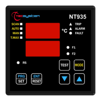
Vis. programming display
PRG programming
Relay test
The ALARM and TRIP relays switch only when the set temperature thresholds are exceeded.
The FAULT contact, programmed in failsafe mode (default YES), opens (11-12) when the equipment is supplied only if
the unit detects no fault on switching on, and stays in this condition until one of the following events occurs:
Data memory fault (Ech message).
Pt100 sensor fault (FCC short-circuited sensor, FOC interrupted sensor or Fcd quick temperature increase)
CAL damage to the measurement circuit.
Insufficient supply voltage.
During the power on reset after programming (PRG), displaying the data (VIS) and test relay.
The FAULT failsafe can be disabled selecting FAULT failsafe "NO" see step 30-31 programming page 15.
NOTE: do not connect the FAULT relay to the transformer tripping circuit to avoid unwanted system interruptions.
FAULT AND RESET MESSAGE SEQUENCE
Find below the sequence of fault messages and RESET function condition.
1) ECH
2) CAL
3) FCD
4) ERR PT
The FAN1 and FAN2 contacts can be used to control the cooling fans, or they can be inserted in the conditioning system of
the transformer room, see paragraph Fan control on page 18.
NOTE: always disconnect the unit before performing any electrical connections.
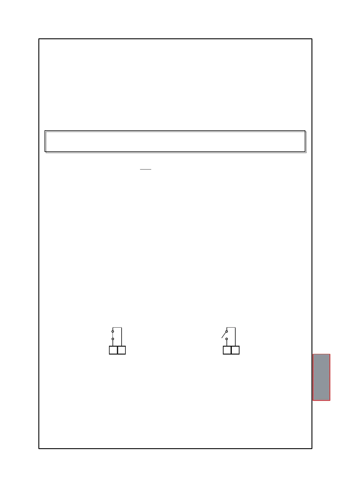
FAULT 11-12 NC: ALARM FAULT OR POWER OFF
FAULT 11-12 NO: POWER ON OR NO FAULT
FAULT CONTACT OPERATION (failsafe enabled)
eeprom fault
measurement circuit fault
quick temp. increase fault
FCC or FOC sensor fault
erasable message
erasable message
resettable condition
non-resettable condition