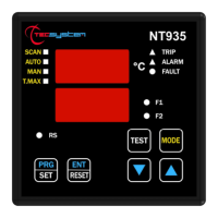
DISPLAY
The first display is dedicated to temperatures
The second display to the monitored channel.
When switching the device ON or following a reset, the display shows: the NT935-4 control unit model, sensor type, VER
"00" (firmware version), BAS (no option) or AD and temperature range.
Pressing the MODE key, the display modes can be set:
SCAN: the monitoring unit displays all the activated (°C) and deactivated (NO) channels scanning every 2 seconds.
AUTO: the monitoring unit displays the hottest channel automatically.
MAN: manual reading of the channel temperature using the up/down .
T.MAX: the monitoring unit displays the highest temperature reached by the sensors and any situation of: alarm or fault
occurred after the last reset. Select channels with cursors , reset values with RESET.
OPERATING PROGRAM CONTROL
To control the protection levels programmed, press the PRG key twice to access the VIS display mode. By repeatedly
pressing the PRG key, you can scroll through all the previously loaded values in sequence.
After 1 minute's keyboard inactivity, the programming display procedure is automatically abandoned.
To stop the display, press the ENT key.
NOTES ON SCAN AND MAN FUNCTIONS
During the SCAN and MAN modes, the operation of the NT935 can be displayed.
1) RUN cPU:
This message appears when the unit operates regularly without any system error.
2) Ech Err:
This message appears when a damage in the EEPROM memory is detected.
Pressing Reset will cancel the message and restore the original default parameters, listed in the programming
paragraph on pages 14-15. Return the control unit to TECSYSTEM for repair.
3) CAL Err:
This message appears when damage is found in the measurement circuit.
The temperature values displayed might be incorrect. Return the control unit to TECSYSTEM for repair.
4) Pt Err :
This message appears when it is detected that one or more PT100 sensors are not working correctly, FOC, FCC
and FCD indications in the temperature sensor diagnostics paragraph on page 17. In case of Err the FAULT relay
will be de-energised.
The above messages will be displayed following the 1-2-3-4 priority stated.
NOTE: regardless of the display mode, in case of a sensor fault (fcc, foc or fcd), the control unit will automatically switch to
SCAN (PRIVILEGED SCAN) mode, immediately allowing you to see the fault on the relative channel CH. (Mode key is
disabled).
LED TEST
We suggest carrying out the control unit LED test regularly.
For this operation, press the TEST key briefly; all the displays turn on for 2 seconds.
If one of the LEDs does not work, please return the control unit to TECSYSTEM for repair.
ALARM RELAY TEST
This function allows you to carry out a test of the relay operation without having to use further devices. To start the test
procedure, keep the TEST button pressed for about 5 seconds: TST appears for 2 seconds, confirming you have entered the
Relay Test mode.
The LED that is lit shows the relay to be tested; use the cursors to select the desired relay.
Press the SET and RESET keys to energise and de-energise the relay to be tested; the display will show ON-OFF.
After 1 minute's keyboard inactivity, the RELAY TEST procedure will be automatically abandoned.
To stop the RELAY TEST procedure, press the TEST key.
Alternatively, you can use the PT100 simulator model: SIM PT100.
ALARM RELAY SILENCING
If you want to silence the ALARM signal press the RESET key: the relay de-energises and the ALARM LED, which was
fixed, will start flashing. Silencing is automatically disabled when the temperature goes below the ALARM threshold.