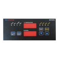
EasyManua.ls Logo

TECSYSTEM NT579 User Manual

TECSYSTEM NT579
48 pages
To Next Page IconTo Next Page
To Previous Page IconTo Previous Page
Page #14 background imageLoading...
Page #14 background image
14
NT579-NT579 RS485
TECSYSTEM SHANGHAI
POLLING FREQUENCY
The max. time to give an answer to a calling never exceeds 1 second; therefore
we suggest not to use polling frequencies with lower duration.
CRC CALCULATION
This protocol includes 2 CRC-16 bytes in each transmission. The characteristic
polynomial (11000000000000101B) is used for the calculation and the result is
“hung” at the end of the package. The polynomial is used in the reverse order
with the most significant bit suppressed because useless for calculation.
PARAMETER DESCRIPTION
A - 16-bit register
AL - At low side
AH - At huigh side
i,j, - KWH METERS
(+) - EXCLUSIVE OR
Di - Frame data «i»th of the packet
N - number of byte of the packet excluded 2 belonging to CRC
G - Polynomial : 1010-0000-0000-0001
shr - right shift
ALGORITHM
1) 0xFFFF -> A
2) 0 -> i
3) 0 -> j
4) Di (+) AL -> AL
5) j +1 -> j
6) shr A
7) if carry then G (+) A -> A
8) if NOT j=8 then go to 5
9) i +1 -> i
10) if NOT i = N then go to 3
11) A -> in CRC (result is in the order L,H)
CODE 16
(10)
.
Request:
Slave address, code 16
(10)
, Starting address HI, Starting address LO, Num-
ber of Point HI, Number of Point LO, Byte count, Data HI, Data LO…….,
Crc LO, Crc HI.
The alarm thresholds (registers 3-4-5-6) are written only for channel L1
Question and Answer IconNeed help?

Do you have a question about the TECSYSTEM NT579 and is the answer not in the manual?

TECSYSTEM NT579 Specifications

General IconGeneral
Frequency50/60 Hz
Operating temperature-20°C to 60°C
Humidity90% non-condensing
Serial portRS485 Modbus RTU
Input Voltage24 VDC
Protection ClassIP20
Storage temperature-20..+70 °C
InputsVoltage 0..10V, Current 0/4..20mA
Sampling rate1 sample/second
DisplayLCD 2 lines x 16 characters
Current Consumption10 W

Summary

NT579 Technical Specifications

Supply

Rated power supply voltage range.

Inputs, Communication, and Outputs

Details on sensors, Modbus RTU, and relay outputs.

Product Performance and Display

Tests and Performances

Compliance, electrical, environmental, and physical test data.

Display and Data Management

Unit display features and data handling capabilities.

Installation and Connections

Mounting and Supply

Panel mounting instructions and power supply notes.

Electrical Connections for Alarms and Ventilation

Wiring for output relays and fan control.

Sensor Handling and Diagnostics

Temperature Sensor Connection and Transfer

Wiring and signal transfer cable requirements.

Temperature Sensor Diagnostics

Fault detection (Fcc, Foc, Fcd) and reset procedures.

Unit Diagnostics and Control

Programmed Data and Circuit Diagnostics

Handling Ech and Cal errors.

Temperature and Fan Control

Alarm/trip activation and fan control logic.

Fan Test

Using HFn for periodic fan self-testing.

User Interface Operations

Display Modes

Cycling through SCAN, AUTO, MAN, T.MAX modes.

Program Control and Viewing

Checking programmed values and navigating menus.

Advanced Operations and Notes

Program Mode Control and Lamp Test

Entering programming and testing LEDs.

Alarm Silencing and Important Notices

Silencing alarms and precautions during insulation testing.

Remote Programming Considerations

Threshold settings and data storage for remote operations.

Programming Procedures

Parameter Programming Steps

Step-by-step guide for configuring unit parameters.

Modbus Communication Setup

Modbus Configuration

Setting address, baud rate, and parity.

Modbus Introduction and Working Notes

Overview of Modbus module and operational requirements.

Modbus Interface Details

Front Panel Overview

Description of front panel controls and indicators.

Modbus Data Transmission and Connections

RS485 wiring and data transmission methods.

Data Frame Structure

Format of data frames in Modbus communication.

Modbus Protocol Specifications

Data Packet Structure

Format of Modbus requests and responses.

Function Codes and Error Codes

Supported function codes and exception error types.

Modbus CRC, Parameters, and Codes

CRC Calculation and Algorithm

Method for CRC calculation in Modbus.

Parameter Descriptions

Definitions of Modbus parameters.

Code 16 (Writing Registers)

Request/response format for writing registers.

FCD Functionality

FCD Function Details

Dynamic monitoring for fast temperature changes.

FCD Sensitivity and Fault Handling

Adjusting sensitivity and managing FCD faults.

Electrical Connections

PT100 Sensor Wiring

Diagram for connecting PT100 sensors.

Control Output and Power Wiring

Wiring for relays, fan, and power supply.

RS485 Output Wiring

Connection for RS485 digital output.

Warranty and Disposal

Warranty Information

Product warranty terms and conditions.

Waste Disposal (RAEE)

Symbol and instructions for environmentally sound disposal.

Related product manuals