Do you have a question about the Tecumseh LAV35 and is the answer not in the manual?
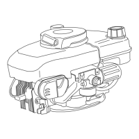
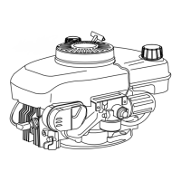
Locating and interpreting engine model, specification, and serial numbers for identification.
Decoding the meaning of letters and numbers in engine model designations.
Guidelines for selecting detergent oil, multigrade oil, and recommended oil change intervals.
Simple procedures to identify different types of Tecumseh carburetors.
Guidelines for pre-setting and adjusting carburetor mixture screws for proper operation.
Table of main and idle pre-set adjustments for various Tecumseh and Walbro carburetor models.
Procedure for making final mixture adjustments on non-emission engines for optimal running.
Detailed steps for disassembling float style carburetors, including needle and bowl removal.
Instructions for disassembling diaphragm carburetors, including cover, diaphragm, and needle seat removal.
Method for checking and adjusting float height for proper carburetor operation and engine starts.
Inspection of carburetor components after disassembly, including shafts, screws, and ports.
Guidance on diagnosing governor-related problems like hunting and overspeeding.
Immediate actions and checks for engines running too fast, including disassembly for inspection.
Troubleshooting steps for engine RPM instability (surging) and governor adjustments.
Detailed steps for adjusting the governor lever and clamp for proper speed control.
Specific governor adjustment steps for short block installations prior to 1977.
Procedures for removing and replacing governor spool, gear, or shaft.
Information on different speed control types, linkage attachment, and R.P.M. checks.
Adjustment procedure for snap-in style speed controls using bendable tabs.
Procedure for adjusting high speed RPM on medium frame vertical engines.
Setting governed and non-governed idle RPM, and ensuring proper throttle plate function.
Adjusting high speed RPM on medium frame vertical engines using a specific tool.
Procedures for diagnosing and repairing starter problems, including disassembly.
Detailed explanation of how the starting circuit and electric starters function.
Flowchart to diagnose electrical starter circuit problems from 'will not turn' to 'stalls under load'.
Flowchart to diagnose electrical charging circuit issues, checking voltage and component continuity.
Procedures for testing starting and charging circuits using electrical testers and voltmeters.
Tests for voltage at the starter terminal, wiring continuity, and engine over-turnability.
Testing procedures for various charging systems, including 350 milliamp systems.
Procedure for removing the flywheel, noting the need to relieve brake pressure first.
Service procedures for the brake lever and pad assembly on bottom surface systems.
Detailed breakdown of the four piston strokes and their role in the engine's power cycle.
Description of lubrication systems for horizontal and vertical shaft engines, including oil dippers and plunger pumps.
Troubleshooting guide for common engine operation issues like knocks, overheating, surges, and oil consumption.
Procedures for testing engine components and diagnosing problems like knocks and overheating.
Causes and checks for engine knocking, including loose components, flywheel key, and ignition timing.
Troubleshooting steps for engine overheating, including load reduction, oil checks, and cooling fins.
Procedures for engine disassembly and component servicing.
Step-by-step guide for disassembling engine models, including flywheel and cylinder head removal.
Inspection and measurement of pistons, rings, and connecting rods, including side and end gap clearance.
Inspection of crankshafts and camshafts for wear, scoring, and alignment of timing marks.
Service procedures for ball bearings on crankshafts and cylinder covers.
Table of torque specifications for various engine models, covering bolts, nuts, and component assembly.
| Horsepower | 3.5 HP |
|---|---|
| Fuel Type | Gasoline |
| Starting System | Recoil |
| Engine Type | 4-cycle, air-cooled |
| Bore | 2.5 in (63.5 mm) |
| Ignition System | Solid-state magneto |