EasyManua.ls Logo

Tecumseh MV 100 S - User Manual

Tecumseh MV 100 S
109 pages
Print Icon
To Next Page IconTo Next Page
Loading...
2
BH 37 E-45040E SER 5 174 C
A. FOREWORD
This manual contains information required to service or
repair all Tecumseh Italian built engines.
For exploded views of particular engines or component
part numbers, refer to the Tecnamotor and Tecumseh
Europa Spare Parts Catalogue.
When ordering spares from your authorized Tecumseh
Dealer, please quote the entire model and specification
number. These numbers are stamped on the engine as
shown below.
Always insist on genuine Tecumseh replacement parts.
ENGINE CODE
SPECTRA 37 E-38000 SER 5 174 A
MODELLO
SPECIFICA
NUMERO DI SERIE
ANNO DI COSTR.
GIORNO DI COSTR.
TURNO
BH 37 E-45040E SER 5 074 C
MODELLO
SPECIFICA
NUMERO DI SERIE
ANNO DI COSTR.
GIORNO DI COSTR.
TURNO
MV 100 S E-16000C SER 5 074 C
MODELLO
SPECIFICA
NUMERO DI SERIE
ANNO DI COSTR.
GIORNO DI COSTR.
TURNO
SPECTRA 37 E-38000 SER 5 174 A
MV 100 S E-16000C SER 5 174 C
S
S
S
S
S
S
174
174
www.mymowerparts.com
For Discount Tecumseh Engine Parts Call 606-678-9623 or 606-561-4983

Table of Contents

Question and Answer IconNeed help?

Do you have a question about the Tecumseh MV 100 S and is the answer not in the manual?

Summary

A. FOREWORD

ENGINE CODE

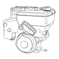
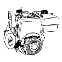
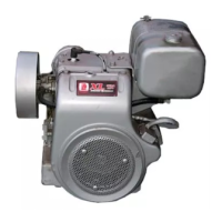
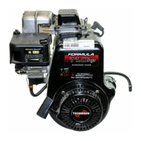
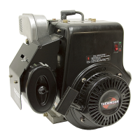
Identifies engine model and specification numbers.

SERVICE BULLETIN

2-stroke engines - running in and oil requirements

Details running-in and oil requirements for 2-stroke engines.

B. CHECK-UP BEFORE REPAIR

1. GENERAL

General checks for engine non-starting and fuel/oil mixture.

2. RECOIL STARTER (CHOKE)

RECOIL STARTER (PRIMER)

Procedure for starting engine using the primer recoil starter.

3. CHECK-UP

a) STARTER

Checking starter engagement, rope condition, and compression.

b) COMPRESSION

c) IGNITION

Checking spark plug for spark and potential ignition faults.

e) EQUIPMENT

Hard Starting, Kickback, Failure to Start

Common equipment-related issues causing starting problems.

C. STARTER

1. RECOIL STARTER

Disassembly and checking of recoil starter components.

2. SIDE MOUNTED STARTER HORIZONTAL ENGAGEMENT TYPE (LAV, BV)

Disassembly

Reassembling

Fault checking

Checks for recoil issues like non-recoil or gear engagement.

3. SIDE MOUNTED STARTER VERTICAL ENGAGEMENT USA TYPE

Disassembly:

Procedures for disassembling the vertical engagement starter.

Assembly

Correct assembly of rope

Steps for correctly assembling the rope into the starter.

4. A - STYLIZED RECOIL STARTER (Fig 28-A)

B - INTEGRAL RECOIL STARTER (Fig 28-B)

Details for integral recoil starter types.

C - STYLISED STARTER WITH PLASTIC WEDGE (Fig. 28-C)

DISASSEMBLY;REASSEMBLY

Steps for disassembling and reassembling the plastic wedge starter.

5. 12 VOLT ELECTRIC START SYSTEM

a) BATTERY

Battery checks, charging, and maintenance for electric start systems.

b) ALTERNATOR

Air gap setting

Procedure for setting the air gap on the alternator.

c) STARTER MOTOR TROUBLESHOOTING

ARMATURE CHECK

How to check the starter motor armature for faults.

D. FLYWHEEL BRAKE SYSTEM

WIRING DIAGRAMS (Electric Start Systems) (Fig 3).

Wiring diagrams for electric start systems.

FLYWHEEL REASSEMBLY (Fig 5)

CONTROL SWITCH (Fig 7,A)

How to check and replace the brake control switch.

E. IGNITION SYSTEM

REMOVAL OF FLYWHEEL (NOT MV OR BH TYPE)

Instructions for removing the flywheel on specific engine types.

CHECKING INTERNAL PARTS

To replace breaker points

Procedure for replacing ignition breaker points.

Cleaning points

COIL INSPECTION

How to inspect the ignition coil for defects.

2. CONVENTIONAL IGNITION SYSTEM EXTERNAL COIL BV SERIES

CONDENSER CHECKING:

Checking the ignition condenser for faults.

3. IGNITION TIMING

FOUR STROKE TIMING (Points Ignition)

Procedure for setting ignition timing on 4-stroke engines.

4. SOLID STATE IGNITION SYSTEM (CDI)

SOLID STATE IGNITION OPERATION

Explanation of how the solid state CDI ignition system operates.

4 A. GROUND TO GO IGNITION UNIT (FLYMO MV100 S)

5. SPARK PLUG (Fig. 26)

Checking, cleaning, and replacing the spark plug.

F. AIR FILTERS

1. POLYURETHANE TYPE AIR CLEANER

Maintenance of polyurethane foam air cleaner elements.

2. MUFFLER ON POLYURETHANE AIR CLEANER

DISASSEMBLY AND MAINTENANCE

How to disassemble and maintain the muffler on the air cleaner.

4. CLEAN.ASP.AIR

BV ENGINES STANDARD

Maintenance of the standard Clean-Asp-Air filter on BV engines.

6. AIR CLEANER FOR FLYMO

Maintenance Instructions (Fig 10):

Instructions for maintaining Flymo Turbo air filters.

7. DUAL POLYURETHANE AIR CLEANER WITH SNORKEL (Fig. 11)

Service filter elements

Service intervals and procedures for dual polyurethane filter elements.

HORIZONTAL CRANKSHAFT ENGINES

VERTICAL CRANKSHAFT ENGINES DUAL ROUND SHAPED AIR CLEANER (Fig 13 A)

Installation of felt pads and elements for dual round air cleaners.

9. AIR CLEANER WITH AIR INTAKE FROM THE BLOWER HOUSING

FILTER REPLACEMENT

Steps for replacing foam elements in blower housing air cleaner.

10. AIR CLEANER INVERTED FLUX FOAM TYPE

FOAM REPLACEMENT

Procedure for replacing foam elements in inverted flux air cleaners.

11. CONICAL AIR CLEANER

PAPER CARTRIDGE REPLACEMENT

How to replace the paper cartridge in a conical air cleaner.

G. CARBURETTORS

DIAPHRAGM CARBURETTOR (Fig. 1)

Description and operation of diaphragm carburettors.

2. DIAPHRAGM CARBURETTOR

a) ADJUSTMENT OF DIAPHRAGM CARBURETTOR

How to adjust diaphragm carburettors with variable jets.

c) SERVICING DIAPHRAGM CARBURETTOR

Standard diaphragm carburettor

Cleaning and servicing standard diaphragm carburettors.

d) DIAPHRAGM CARBURETTOR WITH PRIMER

Non-return valve fails to operate (brass type pressed in valve).

Troubleshooting and replacing the non-return valve.

3. FLOAT STYLE CARBURETTORS

a) ADJUSTMENT (ADJUSTABLE JET) (FIG 14)

Adjusting float carburetors with adjustable jets.

b) OPERATIONS ON FLOAT CARBURETTORS

Brass type float

Checking and adjusting the float level for brass type floats.

d) ALTERNATIVE STYLE PRIMER START FLOAT CARBURETTORS (Fig. 26)

e) NEW FLOAT (Height Adjustment)

Adjusting float height for new carburetor models.

H. GOVERNORS

1. PNEUMATIC GOVERNOR FOR 2 STROKES

Description of pneumatic governors for 2-stroke engines.

c) GOVERNORS FOR AV AND MV MODELS

To adjust the speed operate as follows:

Procedure for adjusting engine speed on AV and MV governors.

2. MECHANICAL GOVERNORS FOR FOUR STROKE ENGINES

b) STANDARD GOVERNOR (FIG 8)

Description of the standard mechanical governor.

3. GOVERNOR LINKAGE HORIZONTAL CRANKSHAFT ENGINES (HBL-BHK-BHT & P VERSIONS)

c) SPEED ADJUSTMENT (Fig 10 & 11)

Adjusting engine speed for horizontal crankshaft governors.

4. GOVERNOR LINKAGE FOR HBP;G AND BHG ENGINES

b) ASSEMBLY AND ADJUSTMENT

Assembling and adjusting governor linkage for specific engine models.

5. GOVERNOR LINKAGE FOR FOUR STROKE ENGINES WITH VERTICAL CRANKSHAFT

c) SPEED ADJUSTMENT (Fig. 15)

Adjusting engine speed for vertical crankshaft governors.

d) NEW GOVERNOR LEVER AND CLAMP WITH PHILLIPS HEAD. LEFT HAND THREAD ON 4-STROKE VERTICAL SHAFT ENGINES

e) GOVERNOR;PLATE FOR PRIMER CARBURETTOR

Speed adjustments for primer carburettors on governor plates.

f) HIGH SPEED CATEGORIES

g) GOVERNOR LEVER MOUNTING SYSTEM

Different systems for mounting governor levers.

I. TWO-STROKE MECHANICAL ENGINE PARTS

1. UNIBLOCK ENGINES (AV520-600-750-125)

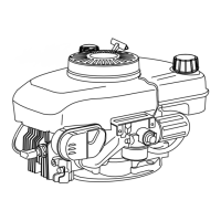
Introduction to uniblock engine components.

Inspection of seals

c) INTERNAL INSPECTION

Internal inspection procedures after seal checks.

d) MAIN BEARING

Reassembly of engine

Steps for reassembling the engine after main bearing work.

e) OVERSIZED PISTONS FOR 2 STROKE ENGINES

2. MONO BLOCK ENGINES - MV100 S

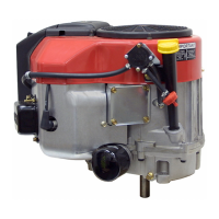
General information about Mono Block MV100S engines.

b) REMOVAL OF FLYWHEEL

c) ENGINE BLOCK DISASSEMBLY

Procedures for disassembling the engine block.

d) REMOVAL AND REFITTING OF CONNECTING ROD & PISTON ASSEMBLY

f) SHROUD BASE REASSEMBLY

Steps for reassembling the shroud base.

3. ALTERNATIVE VERSIONS (AV85 S, EARLIER MV100 S).

2 - STROKE ENGINE - SPECIFICATIONS

Boring

Engine boring specifications for various models.

2-STROKE ENGINE -SPECIFICATIONS

Crankshaft bearing seat diam. - flywheel side

Specifications for crankshaft bearing seat diameter.

2-STROKE ENGINES PRODUCED FROM 1985;86 TO PRESENT

Boring

Boring specifications for engines produced 1985/86 onwards.

2-STROKE ENGINE SPECIFICATIONS

Crankshaft bearing seat diam. - power intake side

Specifications for crankshaft bearing seat diameter.

2-STROKE ENGINE CLOSING TORQUE SPECIFICATIONS

AV-MV TYPE ENGINES

Closing torque specifications for AV-MV type engines.

L. MECHANICAL PARTS OF 4 STROKE ENGINES

2. COMPRESSION CHECK

Procedure for checking engine compression.

Valve seats

Check the tappet clearance

How to check and adjust tappet clearance.

4. DISASSEMBLING CYLINDER, PISTON AND RINGS

a) ENGINES LAV-BV-HS BVS VANTAGE PRISMA SYNERGY SPECTRA, FUTURA

Disassembly instructions for specific engine models.

5. INTERNAL INSPECTION

a) CYLINDER

How to inspect the cylinder bore and bearings for wear.

d) CONNECTING RODS (Fig. 17)

Conrods for engines with horizontal crankshaft

Features of conrods for horizontal crankshaft engines.

e) PISTON RINGS AND PIN

Check piston for damage.

Checking piston for damage, wear, and ovality.

Piston assembly (Figs 24 & 25)

Piston pin

How to remove and replace the piston pin.

f) CAMSHAFT

Compression release

Explanation of the compression release mechanism on 4-stroke engines.

g) LUBRICATION

h) MECHANICAL GOVERNOR

Description and service of the standard mechanical governor.

Oleomatic Governor (Fig. 34)

i) CRANK CASE BREATHER

Checking the crankcase breather valve and body.

6. REASSEMBLY

b) CYLINDER

Installing the cylinder with different bearing types.

c) OVERSIZED PISTONS FOR 4-STROKE ENGINES

d) PISTON AND RINGS

Fitting piston rings and expanders correctly.

e) PISTON AND CONNECTING ROD (FIG 49)

For correct assembly, operate as follows:

Steps for correctly assembling the piston and connecting rod.

f) CAMSHAFT - OIL PUMP - COVER

On engines with aluminium bearings

Crankcase cover installation for engines with aluminium bearings.

g) MOUNTING FLANGE FOR ENGINES WITH LATERAL PTO

7. OHV ENGINES

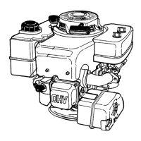
Introduction to OHV engine service and valve train.

Reassembly

SETTING THE VALVE LASH

b) VALVE SERVICE

Valve seats

How to regrind and service valve seats.

4-STROKE ENGINE SPECIFICATIONS

Engine displacement

Engine displacement specifications for various models.

4-STROKE ENGINE SPECIFICATIONS

Crankshaft bearing diameter (flywheel side)

Specifications for crankshaft bearing diameter.

4-STROKE ENGINE CLOSING TORQUES (BV-BVL-BVS-VANTAGE-PRISMA-SYNERGY- PREMIER-SPECTRA-FUTURA)

4-STROKE ENGINE CLOSING TORQUES BH ALL TYPES

Conrod fastening screw

Torque specification for conrod fastening screws.

M. TROUBLESHOOTING

ENGINE DOES NOT START OR HAS DIFFICULTY STARTING

Symptoms and causes for engine not starting or difficult starting.

EQUIPMENT TROUBLE

1;1 Engine does not start or is slow in starting.

Engine not starting or starting slowly due to control cable issues.

EQUIPMENT TROUBLE

1;6 The machine vibrates.

Machine vibration issues caused by unbalanced blade or loose bolts.

ENGINE - POWER SUPPLY UNIT TROUBLE

2;1 The engine starts up and stops after a short time.

Engine starting and stopping due to fuel supply issues.

TROUBLE CAUSED BY ENGINE - POWER SUPPLY UNIT

2;7 Engine runs irregularly at no-load or does not keep up idling (2000 rpm).

Irregular engine running due to air intake or regulator issues.

TROUBLE CAUSED BY ENGINE - IGNITION UNIT

3;1 Engine does not start.

Engine not starting due to ignition system faults.

TROUBLE CAUSED BY ENGINE - ELECTRIC STARTER UNIT

4;1 Engine does not start with E.S., starts correctly with pull start-up.

Engine not starting with electric starter but works with pull start.

TROUBLE CAUSED BY ENGINE - MONOBLOCK ENGINE UNIT

5;1 Engine does not start or starts with great difficulty.

Engine not starting or starting with difficulty due to scaling.

TROUBLE CAUSED BY ENGINE - MONOBLOCK ENGINE UNIT

5;7 Engine does not start. It idles without compression.

Engine not starting with no compression due to broken conrod.

WARRANTY POLICY

WARRANTY DESCRIPTION

Description of the warranty coverage provided by Tecumseh Europe.

NORMAL WEAR

WARRANTY MANAGEMENT

Process for managing warranty claims and approvals.

SPECIAL TOOLS

670297 (*) thickness gauge for 0.3 mm flywheel air gap

Tool for measuring flywheel air gap on electronic ignition systems.

670169 (*) flywheel removal bolt

88841004 (*) tool for mounting compression rings

Tool for mounting piston compression rings.

Tecumseh MV 100 S Specifications

General IconGeneral
Max RPM3600 RPM
Starting SystemRecoil Starter
Horsepower3.5 hp
Fuel TypeGasoline
CarburetorFloat Type
Ignition SystemMagneto
Shaft TypeVertical

Related product manuals