EasyManua.ls Logo

Teka Airtech P10 - User Manual

Teka Airtech P10
28 pages
Print Icon
To Next Page IconTo Next Page
Loading...
Operating instructions
(Translation of the original operating instructions)
Airtech P10
TEKA Absaug- und Entsorgungstechnologie GmbH, Industriestraße 13, D-46342 Velen,
Tel.: +49 2863-9282-0, E-Mail: info@teka.eu, www.teka.eu
1

Questions and Answers

Summary

1. General

2. Description of the system elements

2.1. Illustration of the system elements

Diagram showing the various components of the Airtech P10 unit with numbered parts.

2.2. Functionality of the system

Explains how the filter unit sucks in, filters, and returns polluted air.

2.3. Intended use

Defines the purpose of the filter unit for metal processing fumes and welding smoke.

2.4. System extensions; distinctions between versions

Discusses the option of using a dust discharge unit instead of a collecting tank.

3. Safety instructions

3.1. Definition of the hazard symbols

Explains the meaning of WARNING, CAUTION, NOTICE, and information symbols used in the manual.

3.2. General safety instructions

Provides critical safety advice on unauthorized operation, fire hazards, and particle sensors.

4. Storage, transport and installation of the device

5. Commissioning

5.1. Electrical connection

Details on connecting the device to the electrical power supply safely and correctly.

5.2. Precoating of the filter cartridges

Explains the process of pretreating filter cartridges with filter aid for extended service life.

5.3. Connecting the compressed air supply

Instructions for connecting the dry and oil-free compressed air supply required for filter cleaning.

6. Operating the system

6.1. Explanation of the operating elements

Details on the main switch, emergency stop button, stroboscope flash, and signal horn.

7. Maintenance

7.1. Reset to maintenance state

Steps to safely switch off and prepare the unit for maintenance work.

7.2. Cleaning the filter cartridges

Explains the automatic cleaning process for filter cartridges and when replacement is needed.

7.3. Replacing the filter cartridges

Guide on identifying the need for replacement and the procedure for changing filter cartridges.

7.4. Emptying the dust collecting tank

Procedure for safely emptying and replacing the dust collecting container.

7.5. Draining the condensate

Instructions for regularly draining condensation water from the compressed air tank.

7.6. Precoating of new filter cartridges

Details on pre-treating new filter cartridges with precoat consumable for better performance.

8. Dismantling; Disposal

9. Diagnostics and troubleshooting

10. List of spare parts

11. Technical data

12. EC declaration of conformity

13. Training protocol

14. Maintenance intervals

14.1. Usage-related maintenance

Details maintenance tasks that depend on system operation and usage patterns.

14.2. General maintenance

Outlines maintenance tasks independent of system operation, requiring regular checks.

14.2.1. Visual inspection of the device

Procedure for visually inspecting the device for safety defects and proper connections.

14.2.2. Visual inspection of the pipelines for dust deposits

Instructions for checking pipelines for dust deposits and their removal.

14.2.3. Visual inspection of the pneumatic pipes

Steps for visually inspecting the pneumatic pipes for any issues.

14.2.4. Functional test of the device

Steps for performing a functional test of the device to ensure proper operation.

14.2.5. Electrical test of the electrical lines and earthing connections

Guidelines for electrical testing of lines and earthing connections by qualified personnel.

Overview

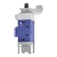
The TEKA Airtech P10 is a filter unit designed for the extraction and filtration of polluted air, specifically targeting dusts and fumes generated from thermal joining and cutting of metals. It is particularly suitable for separating welding smokes from unalloyed, alloyed, and high-alloy chromium-nickel steels, meeting the highest welding fume separation category "W3" according to DIN EN ISO 15012-1.

Function Description:

The core functionality of the Airtech P10 involves drawing in polluted air, which is then purified as it passes through the surface of filter cartridges located in the unit's filter section. The separated dust is collected in a dedicated dust collecting tank. An automatic filter monitoring system continuously assesses the filter cartridges, indicating when cleaning or replacement is necessary. Once purified, the air is returned to the working environment via ejection nozzles. The system incorporates a particle sensor to detect an increase in particles, such as those caused by fire or a filter break, triggering an automatic shutdown of the device for safety. In the event of a fire, the filter area can be filled with extinguishing agent via a C-pipe connection.

Usage Features:

The Airtech P10 is designed for ease of operation and safety. It features a main switch for powering the device on and off, which also functions as an emergency off switch. An emergency stop button allows for immediate shutdown in critical situations, though it's important to note that the unit remains energized when switched off via this button and cannot be restarted until unlocked. The device provides clear status and error messages through a stroboscope flash and a signal horn, with detailed information displayed on the control unit. For specific applications involving stainless steel, the use of an intake element is mandatory to prevent hazards to respiratory tracts. The unit can be extended with an optional dust discharge unit, for which a separate operating manual is available. Proper electrical connection is crucial, requiring a qualified electrician for installation and maintenance, especially if the unit is equipped with a frequency converter. The fan's rotation direction must be checked during commissioning to ensure optimal extraction capacity.

Maintenance Features:

Maintenance of the Airtech P10 is crucial for its longevity and efficient operation. The system incorporates several features to facilitate this. Filter cartridges are reusable and are cleaned automatically when a preset differential pressure value is reached. If the alarm value is not undercut after cleaning, replacement is necessary. New filter cartridges can be pretreated with a filter aid (precoat) during commissioning to extend their service life. This precoating process involves the system being switched on and operating to disperse the filter aid effectively.

Regular maintenance tasks include:

  • Reset to maintenance state: Before any maintenance, the unit must be switched off, disconnected from the power supply, and secured against unauthorized restarting. The compressed air hose must be disconnected, and the compressed air tank emptied by opening the drain valve.
  • Cleaning filter cartridges: This is an automated process. Manual cleaning can also be initiated via the unit control.
  • Replacing filter cartridges: This task requires two people and appropriate disposal containers (PE bags are recommended and available as spare parts). The process involves opening the service door, resolving clamping screws, removing the cartridge holder with the old filter, extracting the displacer, inserting it into a new filter, and reassembling. Only TEKA spare filters should be used to ensure proper functioning.
  • Emptying the dust collecting tank: The dust collecting tank should be emptied when it reaches a maximum of 25% capacity, with a weekly check recommended. This involves cleaning the filter cartridges beforehand, disconnecting power, opening the service door, releasing toggle levers, and carefully removing the tank to dispose of the dust in a PE bag.
  • Draining condensate: Condensation water from the compressed air tank must be drained regularly by slowly opening the drain valve.
  • Visual inspections: Weekly visual inspections of the device, pipelines for dust deposits, and pneumatic pipes are recommended to check for defects, damages, loose connections, corrosion, and dust leaks.
  • Functional tests: Monthly functional tests include switching on the device, checking for error messages, listening for unusual noises, performing manual dedusting, verifying dedusting shock counts, and ensuring sufficient fume/dust collection with a connected machine tool.
  • Electrical tests: Annual electrical tests of lines and earthing connections must be performed by a qualified electrician according to national standards.

The operator is responsible for ensuring that all maintenance work is carried out by authorized and qualified personnel, wearing appropriate respiratory protection (half mask DIN EN 141/143 protection level P3) and handling filter elements cautiously to avoid dust dispersal. Collected dust and filter elements must be stored and disposed of according to national or regional regulations.

Teka Airtech P10 Specifications

General IconGeneral
ModelAirtech P10
TypeCeiling Fan
MountingCeiling
Warranty2 years
Airflow220 m³/min
Noise level50 dB
Blade Span105 cm
Air Delivery220 m³/min
ColorWhite

Related product manuals