Do you have a question about the Teka DW 605 S VR02 and is the answer not in the manual?
Provides an overview of the manual's content, including technical information for related dishwasher models.
Illustrates the water flow routes and components within the dishwasher system.
Presents the electrical connections and color coding for various dishwasher components.
Details the sequence of operations for performing a service test on the dishwasher.
Lists error codes, their meanings, possible causes, and recommended remedies for dishwasher malfunctions.
Provides technical specifications and resistance values for key dishwasher components.
Details control panel layout and service test procedure for LP8 700 and LP8 400 models.
Covers control panel identification and service test initiation for LP8 810, LP8 818, LP8 410, LPM 819, LPZ 417, LVS 831, LPZ 817.
Details control panel layout and service test instructions for LP8 820 and LP8 825 models.
Explains control panel features and service test steps for LP8 840 and LP8 440 models.
Describes control panel layout and service test procedure for LP8 850 (VR02/VR03) models.
Details control panel identification and service test initiation for LP2 140 models.
Covers control panel layout and service test steps for DW8 55 FI, DW8 40 FI, DWM 859 FI, DWZ 57 FI.
Details control panel identification and service test procedure for DW8 57 FI, DW8 58 FI, DW8 41 FI.
Explains control panel layout and service test instructions for DW8 70 FI models.
Details control panel identification and service test procedure for DW9 70 FI models.
Covers control panel layout and service test initiation for DW1 605 FI and DW1 455 FI models.
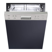
Details control panel identification and service test steps for DW 605 S and DW 455 S models.
Explains control panel layout and service test procedure for LP9 850, LP9 840, LP9 440 models.
| Type | Freestanding |
|---|---|
| Place Settings | 12 |
| Noise Level | 49 dB |
| Drying Efficiency Class | A |
| Delay Start | Yes |
| Half Load Option | Yes |
| Dimensions (H x W x D) | 845 x 600 x 598 mm |