Do you have a question about the Teka DW7 57 FI and is the answer not in the manual?
Identifies and describes the main buttons and indicators on the dishwasher's control panel.
Details common error codes (E1, E3, E4, E6, E7) and their causes or behavior.
Provides voltage and resistance specifications for the inlet valve.
Lists the resistance values of the NTC sensor at various temperatures.
Explains how to test the flowmeter using a multimeter and observing electrical pulses.
Details voltage, resistance, and capacitor specifications for the washing pump.
Provides voltage and resistance specifications for the drain pump.
Lists voltage, power, and resistance specifications for the heater.
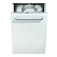
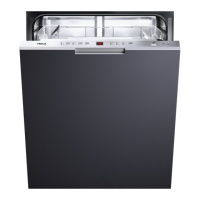
This document serves as a service manual for Teka dishwasher models DW7 57 FI, DW7 41 FI, and LPI 759. It provides essential information for technicians to diagnose and repair these appliances, focusing on the service test, error codes, and electrical components.
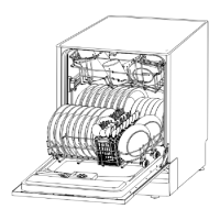
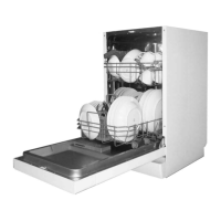
The dishwasher is designed to clean dishes and cutlery through a multi-stage washing process. Users can select various wash programs tailored to different levels of soiling and types of dishes. The control panel, located on the front of the appliance, features an ON/OFF button, a power-on light, a delayed start button, a digital display, salt and rinse aid warning lights, a program button, and a program indicator light. These controls allow users to initiate, pause, and customize wash cycles. The display provides feedback on the current status of the dishwasher, including error codes and the progress of the wash cycle.
A key feature for maintenance is the integrated service test program. This diagnostic tool allows technicians to systematically check the functionality of various components. To activate the test program, the door must be open and the machine off. The technician holds down the Program button and simultaneously presses the POWER button until the machine enters the test program, indicated by "88" on the display, signifying initialization and standby mode. Closing the door then initiates the test sequence.
During the test, the Program button can be used to advance to the next step, except for the inlet valve step, which proceeds automatically. The test program runs through a series of steps, each designed to activate a specific component or function and display a corresponding code.
The dishwasher is equipped with a self-diagnostic system that displays error codes on the control panel to indicate specific malfunctions. These codes are crucial for troubleshooting and maintenance.
The manual includes a detailed wiring diagram and a water circuit scheme, which are indispensable for advanced troubleshooting. The wiring diagram illustrates the electrical connections between various components, including the power switch, rinse aid detector, float switch, salt detector, flowmeter, thermistor, dispenser, door switch, pressure switch for heater, thermostats, drain pump, wash pump, inlet valve, and regeneration valve. This diagram helps technicians trace electrical paths and identify potential wiring faults.
The water circuit scheme provides a visual representation of how water flows through the dishwasher during different stages: inlet water route, regeneration water route, cycle water route, and drain water route. Key components in the water circuit include the air breaker, top spray, upper spray arm, lower spray arm, softener, inlet hose, inlet valve, regeneration valve, washing pump, drain pump, pressure switch, and overflow switch. Understanding this scheme is vital for diagnosing issues related to water intake, circulation, and drainage.
The manual also provides descriptions of individual electrical components:
By utilizing the service test, understanding error codes, and referring to the wiring and water circuit diagrams, technicians can efficiently diagnose and repair issues in Teka DW7 57 FI, DW7 41 FI, and LPI 759 dishwashers, ensuring their proper functioning and extending their lifespan. The detailed information provided in this manual empowers service personnel to perform comprehensive maintenance and troubleshooting tasks.
| Door color | Not applicable |
|---|---|
| Water fill | Cold, Hot |
| Display type | LED |
| Tub material | Metal |
| Built-in display | Yes |
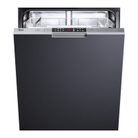
| Appliance placement | Fully built-in |
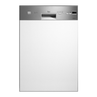
| Control panel color | Stainless steel |
| Cutlery compartment type | Basket |
| Connected load | 1900 W |
| AC input voltage | 220 - 240 V |
| AC input frequency | 50 Hz |
| Water consumption per cycle | 12 L |
| Energy consumption per cycle | 1.05 kWh |
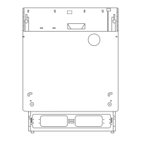
| Installation compartment dimensions (WxDxH) | 600 x 570 x 570 mm |
| Noise level | 49 dB |
| Delay start (max) | 24 h |
| Dishwashing programs | Eco, Quick |
| Number of place settings | 12 place settings |
| Number of washing programs | 9 |
| Number of temperature settings | 4 |
| Depth | 550 mm |
|---|---|
| Width | 596 mm |
| Height | 868 mm |
| Installation compartment height (max) | 870 mm |
| Installation compartment height (min) | 820 mm |