EasyManua.ls Logo

Teka LCZ 837 - User Manual

Teka LCZ 837
7 pages
Print Icon
To Next Page IconTo Next Page
Loading...
Service Manual
MSDW15050
Models:
LCZ 837
LP7 811
LPM 809
LV 831
MLP 800
Contents
1. Introduction .......................................................................................................... - 1 -
2. Control panel ........................................................................................................ - 1 -
3. Service Test ........................................................................................................... - 1 -
4. Error codes ............................................................................................................ - 2 -
5. Wiring diagram ..................................................................................................... - 4 -
6. Water circuit scheme ............................................................................................ - 5 -
7. Electrical components .......................................................................................... - 5 -
Question and Answer IconNeed help?

Do you have a question about the Teka LCZ 837 and is the answer not in the manual?

Summary

Manual Introduction

Appliance Control Panel

Service Test Guide

Appliance Error Codes

Electrical Wiring Diagram

Appliance Water Circuit

Electrical Component Details

Inlet Valve Specifications

Details voltage and resistance specifications for the inlet valve.

NTC Sensor Resistance Table

Provides resistance values for the NTC sensor at various temperatures.

Overview

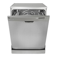
This document is a service manual for Teka dishwashers, specifically models LCZ 837, LV 831, LP7 811, LPM 809, and MLP 800. It provides technical information for service personnel, including how to access the service test, interpret error codes, and details about the wiring diagram, water circuit scheme, and electrical components.

Function Description:

The manual outlines the operation of the dishwasher through a service test, which allows technicians to systematically check various components and functions. The service test sequence includes initialization, inlet valve operation, washing pump and dispenser activation, heating element operation, drain pump activation, and regeneration valve operation. Each step is associated with a specific display code and a description of the expected action and duration. For instance, the "Inlet valve" step (Display "0A") involves opening the inlet valve and feeding 3.6L of water (3.0L in 45 cm models). The "Washing pump and dispenser" step (Display "09") activates the dispenser once and runs the washing pump for 60 seconds. The "Heating element" step (Display "08") runs the washing pump and heating element until the water temperature reaches 57ºC, after which the machine pauses. The manual also details error codes that indicate specific malfunctions, providing guidance for diagnosis and troubleshooting.

Important Technical Specifications:

Electrical Components:

  • Inlet valve:
    • Voltage: 220 - 240 V
    • Resistance: 3.4 - 4.3 kΩ
  • NTC sensor: A thermistor with varying resistance based on temperature:
    • 15°C: 17.48 kΩ
    • 20°C: 12.12 kΩ
    • 25°C: 10 kΩ
    • 30°C: 8.299 kΩ
    • 40°C: 5.807 kΩ
    • 50°C: 4.144 kΩ
    • 60°C: 3.011 kΩ
    • 70°C: 2.224 kΩ
    • 80°C: 1.667 kΩ
    • 85°C: 1.451 kΩ
  • Flowmeter: Designed to send electrical pulses as water passes through it. Can be tested using a multi-meter in Diode testing mode.
  • Washing pump:
    • Voltage: 220 - 240 V
    • Resistance: 131.4 Ω (±10%)
    • Capacitor: 3μF
  • Drain pump:
    • Voltage: 220 - 240 V
    • Resistance: 150 - 220 Ω
  • Heater:
    • Voltage: 230 V
    • Power: 1800 W
    • Resistance: 29.3 Ω ± 1.47 Ω

Water Circuit Scheme:

The manual includes a detailed diagram of the water circuit, illustrating the paths for inlet water, regeneration water, cycle water, and drain water. Key components shown include the top spray, upper spray arm, air breaker, tube, lower spray arm, softener, inlet hose, inlet valve, regeneration valve, washing pump, pressure switch, drain pump, and overflow switch.

Usage Features (Service Test):

The service test is initiated by holding down the "1 hour Program" button and pressing the "POWER" button with the door closed and the machine off. Pressing the "1 hour Program" button again starts the test. During the test, the "Program" button can be used to advance to the next step, except for the inlet valve step.

Maintenance Features (Error Codes and Troubleshooting):

The manual provides a comprehensive list of error codes and their meanings, along with troubleshooting steps:

  • E1: Water filling exceeds pre-set time.
    • Occurs if the inlet valve has been open for 4 minutes but the water quantity (measured by pulses from the flowmeter) has not reached the desired value.
    • Action: The drain pump runs until the flowmeter is motionless for 2 minutes, and all other components stop. The buzzer sounds for 30 seconds, and "E1" is displayed.
  • E3: Heating exceeds pre-set time.
    • Occurs if the heating element has been working for 60 minutes but the water temperature (detected by the NTC sensor) has not reached the desired value.
    • Action: The drain pump runs until the flowmeter is motionless for 2 minutes, and all other components stop. The buzzer sounds for 30 seconds, and "E3" is displayed.
  • E4: Overflow.
    • Occurs if the overflow micro-switch is activated and remains active for longer than 2 seconds. This error has the highest priority.
    • Action: The drain pump runs until the flowmeter is motionless for 2 minutes, and all other components stop. The buzzer sounds for 30 seconds, and "E4" is displayed. After E4 operation, all other errors are invalidated.
  • E6: Open-circuit failure of NTC Sensor.
    • Detected by the controller during the test program.
    • Action: The drain pump runs until the flowmeter is motionless for 2 minutes, and all other components stop. The buzzer sounds for 30 seconds, and "E6" is displayed.
  • E7: Short-circuit failure of NTC sensor.
    • Detected by the controller during the test program.
    • Action: The drain pump runs until the flowmeter is motionless for 2 minutes, and all other components stop. The buzzer sounds for 30 seconds, and "E7" is displayed.

The error code table also indicates which program indicator lights (55", 50", 1h) will be intermittent or off for each error, aiding in visual diagnosis.

Teka LCZ 837 Specifications

General IconGeneral
BrandTeka
ModelLCZ 837
CategoryDishwasher
LanguageEnglish

Related product manuals