USE AND INSTALLATION MANUAL ELFO
30
4.18 INSTALLATION OF PIPES FOR COOLING
The main cause of refrigerant leaks is due to a defect in flaring. Make folders correctly observing the following guidelines:
Cut the copper cooling pipes and the electrical cable
1. Use tubes with appropriate measures the installed unit.
2. Measure the distance between the Indoor and Outdoor Unit.
3. Cut the pipes to a slightly greater length of the measured
distance.
4. Cut the electrical cord 1.5 m longer than the length of the tube.
Removal of copper burrs
1. Completely remove all burrs from the pipe cross section.
2. The machining should be performed with the machinable end
down so that the burrs do not fall inside the copper tube.
Filler positioning
Remove the nuts fixed indoor and outdoor unit, insert them
on the tube, and perform the flanging and the removal of
burrs as previously indicated.
Flaring
Secure the copper tube with a die size indicated in the table.
A. Securing the refrigerator connection
1. Align the pipes.
2. sufficiently tighten the nut with the help of two keys
B. Precautions
An excessive torque can ruin the folder and cause refrigerant
leakage.
INSTALLATION
The presence of air and moisture in the refrigerant system
may have the following side effects:
• Increased pressure in the system
• Increased operating current
• Reduction of the efficiency of cooling (or heating)
• Possible freezing upon in the refrigerant circuit, resulting in
blockage occurring
• Possibility of corrosion caused by the water of part of the
refrigerating system
Therefore, the indoor unit and tubing between the indoor and
outdoor unit must be tested for leaks and
emptied to remove any trace of elements non-condensing
and moisture from the system.
LEAK TESTING
After completing the connection of the refrigerant pipes, run
the tightness test. In the test, to pressurize the tubes using a
nitrogen cylinder.
• Close the valves of the liquid and gas. The nitrogen may
enter the outdoor unit refrigerant circuit, therefore, before
pressurizing the pipes, batten down the taps gas and liquid
side side.
• For each of the refrigerant circuits, acting pressurize the
tubes from the gas exhaust valve:
1. pressurize for 3 minutes at 0.3MPa (3.0 bar).
2. pressurize for 3 minutes at 1.5MPa (15.0 bar). You will be
found a great loss.
3. Pressurize for about 24 hours at 3,0MPa (30.0 bar). You
will be found a small leak.
If the pressure does not drop, the system is in place. If the
pressure drops, you have to find the leak.
• While pressurizing for 24 hours, every change of 1 ° C of
the ambient temperature will result in a variation
of 0,01MPa pressure (0.1 kg / cm2g). It must take this into
account during the test run.
• At points 1 to 3, if the pressure drops, check each joint with
touch, hearing, and soap solution to locate the leak. Then
rerun the coupling or tighten the nut well.
pag. 44
PROVA DI TE NUTA TUBAZIONI E VUOTO
Verif
icare che tutti i collegamenti non presentino alcuna perdita.
La presenza di aria e umidità all’interno del sistema refrigerante può avere i seguenti effetti indesiderati:
• Aumento della pressione del sistema
• Aumento della corrente di esercizio
• Riduzione dell’efficienza di raffreddamento (o riscaldamento)
• Possibile congelamento dell’umidità presente nel circuito del refrigerante, con conseguente blocco dei tubi
• Possibilità di corrosione causata dall’acqua di parti del sistema refrigerante
Pertanto, l’unità interna e le tubazioni tra le unità interne ed esterne devono essere sottoposte a prova di tenuta e
svuotate per rimuovere qualsiasi traccia di elementi non condensanti e di umidità dal sistema.
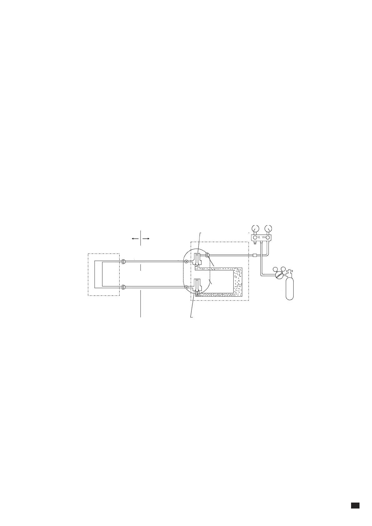
PROVA DI TENUTA
Dopo aver completato il collegamento delle tubazioni del refrigerante, eseguire la prova di tenuta stagna. Nella
prova, mettere in pressione i tubi usando una bombola di azoto come mostrato in figura.
• Chiudere completamente le valvole del liquido e del gas. L'azoto potrebbe entrare nel circuito frigorifero
dell'unità esterna, quindi, prima di pressurizzare i tubi, chiudere bene i rubinetti lato gas e lato liquido.
• Per ciascuno dei circuiti frigoriferi, pressurizzare i tubi agendo dalla valvola di scarico del gas (vedi figura).
1) Pressurizzare per 3 minuti a 0,3MPa (3,0 bar).
2) Pressurizzare per 3 minuti a 1,5MPa (15,0 bar). Verrà trovata una grossa perdita.
3) Pressurizzare per circa 24 ore a 3,0MPa (30,0 bar). Verrà trovata una piccola perdita.
Se la pressione non cala, il sistema è a posto. Se la pressione cala, bisogna individuare la perdita.
• Mentre si pressurizza per 24 ore, ogni variazione di 1°C della temperatura ambiente comporterà una variazione
di pressione di 0,01MPa (0,1 kg/cm2g). Bisogna tenerne conto durante l'esecuzione del test.
• Nei punti da 1) a 3), se la pressione cala, verificare ogni giunto con il tatto, l'udito, e la soluzione saponata per
individuare la perdita. Quindi rieseguire il giunto o stringere bene il dado.
outdoor
flange
hatch
external unite
flange
nitrogen
internal unit
indoor
high
pressure
gauge
low
pressure
gauge
tighten
the clamp
valve 2 way closed
(liquid side)
gas exhaust
valve
valve 3 way
closed
(gas side)
tighten
the clamp
Pressure
reducing
valve
 Loading...