Calibration—475
h. Select 2 ns time marks from the Time-Mark
Generator.
i. CHECK—CRT display for 1 cycle/division, within 2%
from +20°C to +30°C; 1 cycle/division, within 4% from
—15°C to +55° C.
j. ADJUST—C1179 (see Fig. 5-27) with a low-
capacitance screwdriver, for 1 cycle/division.
k. Set the A TIME/D1V switch to 0.01 jus.
I. CHECK—CRT display for 1 cyeie/2 divisions, within
2% from +20°C to +30°C; 1 cycle/2 divisions, within 4%
from —15°C to +55°C.
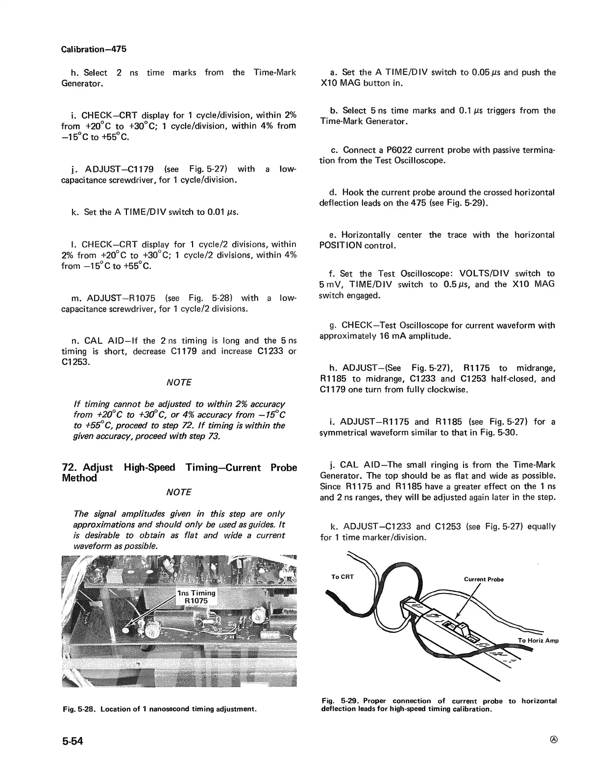
m. ADJUST—R1075 (see Fig. 5-28) with a low-
capacitance screwdriver, for 1 cycle/2 divisions.
n. CAL AID —If the 2 ns timing is long and the 5 ns
timing is short, decrease Cl 179 and increase Cl 233 or
Cl 253.
NOTE
If timing cannot be adjusted to within 2% accuracy
from +20° C to +30° C, or 4% accuracy from —15°C
to +55°C, proceed to step 72. If timing is within the
given accuracy, proceed with step 73.
a. Set the A TIME/DIV switch to 0.05jus and push the
X I0 MAG button in.
b. Select 5 ns time marks and 0.1 jus triggers from the
Time-Mark Generator.
c. Connect a P6022 current probe with passive termina
tion from the Test Oscilloscope.
d. Hook the current probe around the crossed horizontal
deflection leads on the 475 (see Fig. 5-29).
e. Horizontally center the trace with the horizontal
POSITION control.
f. Set the Test Oscilloscope: VOLTS/DIV switch to
5 mV, TIME/DIV switch to 0.5 jus, and the X10 MAG
switch engaged.
g. CHECK—Test Oscilloscope for current waveform with
approximately 16 mA amplitude.
h. ADJUST—(See Fig. 5-27), R1175 to midrange,
R1185 to midrange, Cl 233 and Cl 253 half-closed, and
Cl 179 one turn from fully clockwise.
i. ADJUST—R1175 and R1185 (see Fig. 5-27) for a
symmetrical waveform similar to that in Fig. 5-30.
72. Adjust High-Speed Timing—Current Probe
Method
NO TE
The signal amplitudes given in this step are only
approximations and should only be used as guides. It
is desirable to obtain as flat and wide a current
waveform as possible.
Fig. 5-28. Location of 1 nanosecond timing adjustment.
j. CAL AID—The small ringing is from the Time-Mark
Generator. The top should be as flat and wide as possible.
Since R1175 and R1185 have a greater effect on the 1 ns
and 2 ns ranges, they will be adjusted again later in the step.
k. ADJUST-Cl 233 and Cl 253 (see Fig. 5-27) equally
for 1 time marker/division.
Fig. 5-29. Proper connection of current probe to horizontal
deflection leads for high-speed timing calibration.
5-54