Calibration—475
b. Adjust the CH 1 POSITION control to horizontally
center the dot.
c. Set the Test Oscilloscope: TIME/DIV switch to 1 ms,
VOLTS/DIV switch to 0.5 V, and AC-GND-DC switch to
DC.
d. Connect a X I0 probe from the Test Oscilloscope to
the +50 V test point on the 475 (see Fig. 5-26).
e. Position the trace on the Test Oscilloscope to the
center vertical graticule line.
f. Disconnect the probe from the +50 V test point.
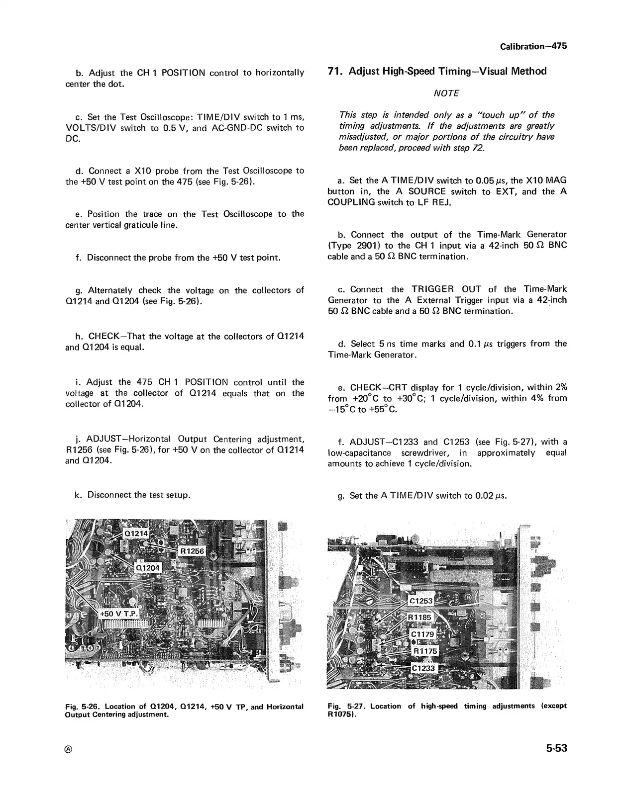
g. Alternately check the voltage on the collectors of
Q1214 and Q1204 (see Fig. 5-26).
h. CHECK—That the voltage at the collectors of G1214
and Q1204 is equal.
i. Adjust the 475 CH 1 POSITION control until the
voltage at the collector of Q1214 equals that on the
collector of Q1204.
j. ADJUST—Horizontal Output Centering adjustment,
R1256 (see Fig. 5-26), for +50 V on the collector of G1214
and G1204.
71. Adjust High-Speed Timing—Visual Method
NOTE
This step is intended only as a "touch u p" o f the
timing adjustments. If the adjustments are greatly
misadjusted, or major portions o f the circuitry have
been replaced, proceed with step 72.
a. Set the A TIME/DIV switch to 0.05 jus, the X I0 MAG
button in, the A SOURCE switch to EXT, and the A
COUPLING switch to LF REJ.
b. Connect the output of the Time-Mark Generator
(Type 2901) to the CH 1 input via a 42-inch 50 £2 BNC
cable and a 50 £2 BNC termination.
c. Connect the TRIGGER OUT of the Time-Mark
Generator to the A External Trigger input via a 42-inch
50 El BNC cable and a 50 El BNC termination.
d. Select 5 ns time marks and 0.1 jus triggers from the
Time-Mark Generator.
e. CHECK—CRT display for 1 cycle/division, within 2%
from +20°C to +30°C; 1 cycle/division, within 4% from
—15°C to +55° C.
f. ADJUST—C l233 and C l253 (see Fig. 5-27), with a
low-capacitance screwdriver, in approximately equal
amounts to achieve 1 cycle/division.
Fig. 5-26. Location of Q1204, Q1214, +50 V TP, and Horizontal Fig. 5-27. Location of high-speed timing adjustments {except
Output Centering adjustment. R1075).
®
5-53