Calibration—475
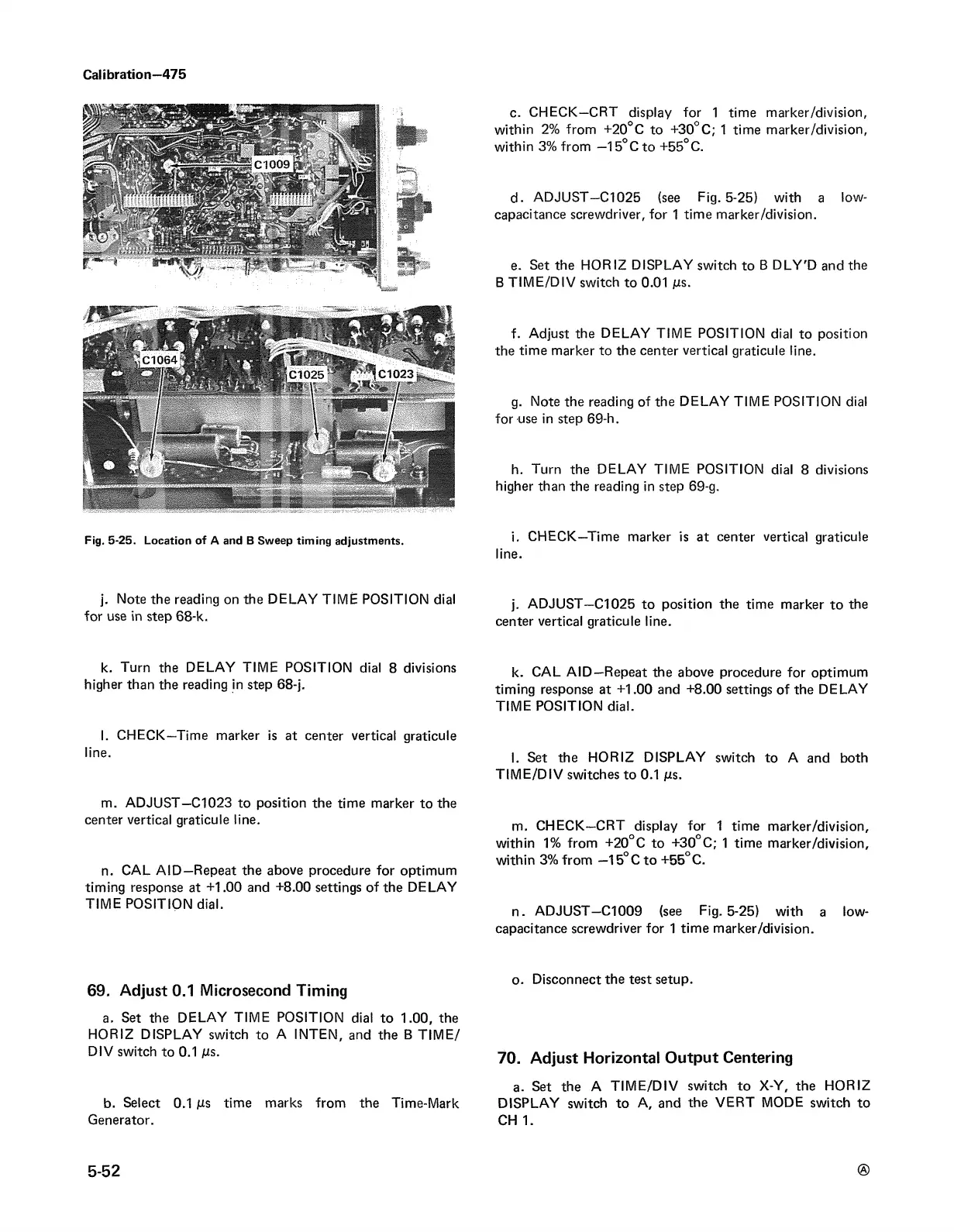
Fjg. 5-25. Location of A and B Sweep timing adjustments.
j. Note the reading on the DELAY TIME POSITION dial
for use in step 68-k.
k. Turn the DELAY TIME POSITION dial 8 divisions
higher than the reading in step 68-j.
I. CHECK—Time marker is at center vertical graticule
line.
m. ADJUST—C1023 to position the time marker to the
center vertical graticule line.
n. CAL A ID —Repeat the above procedure for optimum
timing response at +1.00 and +8.00 settings of the DELAY
TIME POSITION dial.
69. Adjust 0.1 Microsecond Timing
a. Set the DELAY TIME POSITION dial to 1.00, the
HORIZ DISPLAY switch to A INTEN, and the B TIM E/
DIV switch to 0.1 Ms.
b. Select 0.1 ms time marks from the Time-Mark
Generator.
c. CHECK—CRT display for 1 time marker/division,
within 2% from +20°C to +30°C; 1 time marker/division,
within 3% from —15°C to +55°C.
d. ADJUST—C l025 (see Fig. 5-25) with a low-
capacitance screwdriver, for 1 time marker/division.
e. Set the HORIZ DISPLAY switch to B DLY'D and the
B TIME/DIV switch to 0.01 Ms.
f. Adjust the DELAY TIME POSITION dial to position
the time marker to the center vertical graticule line.
g. Note the reading of the DELAY TIME POSITION dial
for use in step 69-h.
h. Turn the DELAY TIME POSITION dial 8 divisions
higher than the reading in step 69-g.
i. CHECK—Time marker is at center vertical graticule
line.
j. ADJUST—C l025 to position the time marker to the
center vertical graticule line.
k. CAL AID —Repeat the above procedure for optimum
timing response at +1.00 and +8.00 settings of the DELAY
TIME POSITION dial.
I. Set the HORIZ DISPLAY switch to A and both
TIME/DIV switches to 0.1 ms.
m. CHECK—CRT display for 1 time marker/division,
within 1% from +20°C to +30°C; 1 time marker/division,
within 3% from —15°C to +55°C.
n. ADJUST—C l009 (see Fig. 5-25) with a low-
capacitance screwdriver for 1 time marker/division.
o. Disconnect the test setup.
70. Adjust Horizontal Output Centering
a. Set the A TIM E/DIV switch to X-Y, the HORIZ
DISPLAY switch to A, and the VERT MODE switch to
CH 1.
5-52