Calibration—475
74. Check A INTEN Timing Accuracy
a. Set the HORIZ DISPLAY switch to A INTEN.
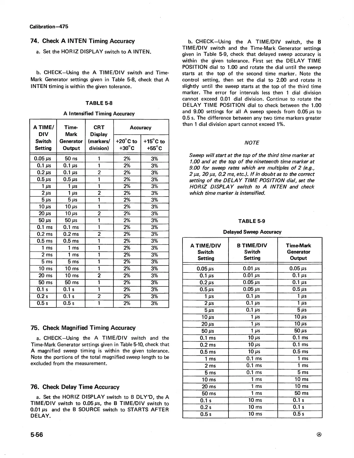
b. CHECK—Using the A TIM E /D IV switch and Time-
Mark Generator settings given in Table 5-8, check that A
INTEN timing is within the given tolerance.
TABLE 5-8
A Intensified Timing Accuracy
A TIM E /
DIV
Switch
Setting
Time-
Mark
Generator
Output
CRT
Display
(markers/
division)
Accuracy
+20° C to
+30° C
+15° C to
+55° C
0.05 jus 50 ns
1 2%
3%
0.1 jus 0.1 jus 1 2%
3%
0.2 jus 0.1 jus
2
2%
3%
0.5 jus
0.5 jus 1
2%
3%
1 JUS 1 JUS 1 2%
3%
2jus
1 JUS
2
2%
3%
5 jus
5 jus 1 2%
3%
10 jus
10 jus
1 2%
3%
20 jus 10 jus 2
2%
3%
50 jus 50 jus
1
2%
3%
0.1 ms 0.1 ms
1
2% 3%
0.2 ms
0.2 ms
2
2% 3%
0.5 ms 0.5 ms
1
2% 3%
1 ms 1 ms 1
2% 3%
2 ms 1 ms
1 2%
3%
5 ms
5 ms
1
2%
3%
10 ms
10 ms
1
2%
3%
20 ms 10 ms 2 2%
3%
50 ms
50 ms 1
2% 3%
0.1 s 0.1 s 1
2% 3%
0.2 s 0.1 s
2
2%
3%
0.5 s 0.5 s 1
2%
3%
75. Check Magnified Timing Accuracy
a. CHECK—Using the A TIM E/DIV switch and the
Time-Mark Generator settings given in Table 5-10, check that
A magnified sweep timing is within the given tolerance.
Note the portions of the total magnified sweep length to be
excluded from the measurement.
76. Check Delay Time Accuracy
a. Set the HORIZ DISPLAY switch to B DLY'D, the A
TIM E /D IV switch to 0.0 5 jus, the B T IM E/DIV switch to
0.01 ms and the B SOURCE switch to STARTS AFTER
DELAY.
b. CHECK—Using the A TIM E/DIV switch, the B
TIM E /D IV switch and the Time-Mark Generator settings
given in Table 5-9, check that delayed sweep accuracy is
within the given tolerance. First set the DELAY TIME
POSITION dial to 1.00 and rotate the dial until the sweep
starts at the top of the second time marker. Note the
control setting, then set the dial to 2.00 and rotate it
slightly until the sweep starts at the top of the third time
marker. The error for intervals less then 1 dial division
cannot exceed 0.01 dial division. Continue to rotate the
DELAY TIM E POSITION dial to check between the 1.00
and 9.00 settings for all A sweep speeds from 0.05 ms to
0.5 s. The difference between any two time markers greater
than 1 dial division apart cannot exceed 1%.
NOTE
Sweep will start at the top of the third time marker at
1.00 and at the top of the nineteenth time marker at
9.00 for sweep rates which are multiples o f 2 (e.g.,
2 ps, 20 ps, 0.2 ms, etc.), if in doubt as to the correct
setting o f the D ELA Y TIM E P OSITIO N dial, set the
H O R IZ DIS P LA Y switch to A IN T E N and check
which time marker is intensified.
TABLE 5-9
Delayed Sweep Accuracy
A T IM E /D IV
B TIM E /D IV
Time-Mark
Switch
Switch
Generator
Setting
Setting Output
0.05 jus
0.01 jus
0.05 ms
0.1 jus
0.01 jus 0.1 jus
0.2 jus
0.05 Ms
0.1 jus
0.5 jus
0.05 jus
0.5 jus
1 JUS
0.1 jus
1 JUS
2 jus
0.1 jus 1 JUS
5 jus
0.1 jus
5 ms
10 jus
1 ms
10 jus
20 jus
1 ms
10 jus
50 jus
1 Ms
50 jus
0.1 ms
10 jus
0.1 ms
0.2 ms
10 jus
0.1 ms
0.5 ms
10 jus 0.5 ms
1 ms
0.1 ms
1 ms
2 ms
0.1 ms
1 ms
5 ms
0.1 ms 5 ms
10 ms
1 ms 10 ms
20 ms
1 ms
10 ms
50 ms
1 ms 50 ms
0.1 s
10 ms 0.1 s
0.2 s
10 ms 0.1 s
0.5 s
10 ms 0.5 s
 Loading...


