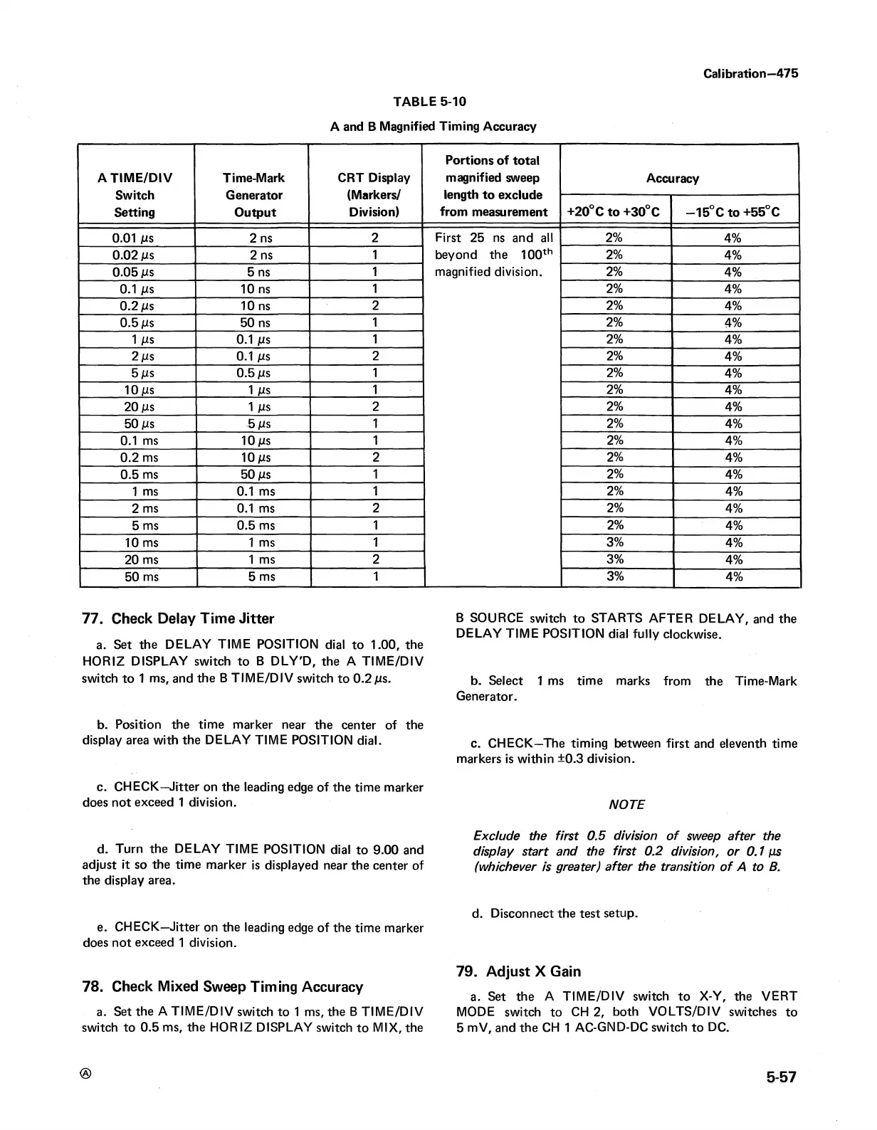
TABLE 5-10
A and B Magnified Timing Accuracy
Calibration—475
A T IM E /D IV
Switch
Setting
Time-Mark
Generator
Output
CRT Display
(Markers/
Division)
Portions of total
magnified sweep
length to exclude
from measurement
Accuracy
+20° C to +30° C
—15°C to +55° C
0.01 jus 2 ns
2 First 25 ns and all
2%
4%
0.02 jus 2 ns
1
beyond the 100th 2%
4%
0.05 jus
5 ns
1
magnified division.
2%
4%
0.1 jus 10 ns
1
2%
4%
0.2 jus
10 ns
2 2%
4%
0.5 jus 50 ns
1
2%
4%
1 jUS
0.1 jus
1
2%
4%
2 jus 0.1 jus
2
2%
4%
5 /is
0.5 jus 1 2%
4%
10 jus 1 /is
1 2%
4%
20 jus
1 Ms
2 2%
4%
50 jus
5 ms
1
2%
4%
0.1 ms
10 jus
1
2%
4%
0.2 ms 10 jus
2 2%
4%
0.5 ms 50 jus
1
2%
4%
1 ms 0.1 ms
1 2%
4%
2 ms
0.1 ms
2
2%
4%
5 ms
0.5 ms
1 2%
4%
10 ms
1 ms
1 3%
4%
20 ms
1 ms 2
3%
4%
50 ms
5 ms
1
3%
4%
77. Check Delay Time Jitter
a. Set the DELAY TIM E POSITION dial to 1.00, the
HORIZ DISPLAY switch to B DLY'D, the A TIM E /D IV
switch to 1 ms, and the B TIM E/D IV switch to 0.2 jus.
b. Position the time marker near the center of the
display area with the DELAY TIM E POSITION dial.
c. CHECK—Jitter on the leading edge of the time marker
does not exceed 1 division.
d. Turn the DELAY TIME POSITION dial to 9.00 and
adjust it so the time marker is displayed near the center of
the display area.
e. CHECK—Jitter on the leading edge of the time marker
does not exceed 1 division.
78. Check Mixed Sweep Timing Accuracy
a. Set the A TIM E /D IV switch to 1 ms, the B TIM E /D IV
switch to 0.5 ms, the HORIZ DISPLAY switch to MIX, the
B SOURCE switch to STARTS AFTER DELAY, and the
DELAY TIM E POSITION dial fully clockwise.
b. Select 1 ms time marks from the Time-Mark
Generator.
c. CHECK—The timing between first and eleventh time
markers is within ±0.3 division.
NOTE
Exclude the first 0.5 division o f sweep after the
display start and the first 0.2 division, or 0.1 ps
(whichever is greater) after the transition of A to B.
d. Disconnect the test setup.
79. Adjust X Gain
a. Set the A TIM E /D IV switch to X-Y, the VERT
MODE switch to CH 2, both VO LTS/DIV switches to
5 mV, and the CH 1 AC-GND-DC switch to DC.
5-57