Calibration—475
b. Apply a 20 mV square wave from the Standard
Amplitude Calibrator to the CH 1 or X input through a
42-inch 50 £2 8NC cable.
c. CHECK—CRT display for 4 divisions of deflection
between the two displayed dots, within 3%.
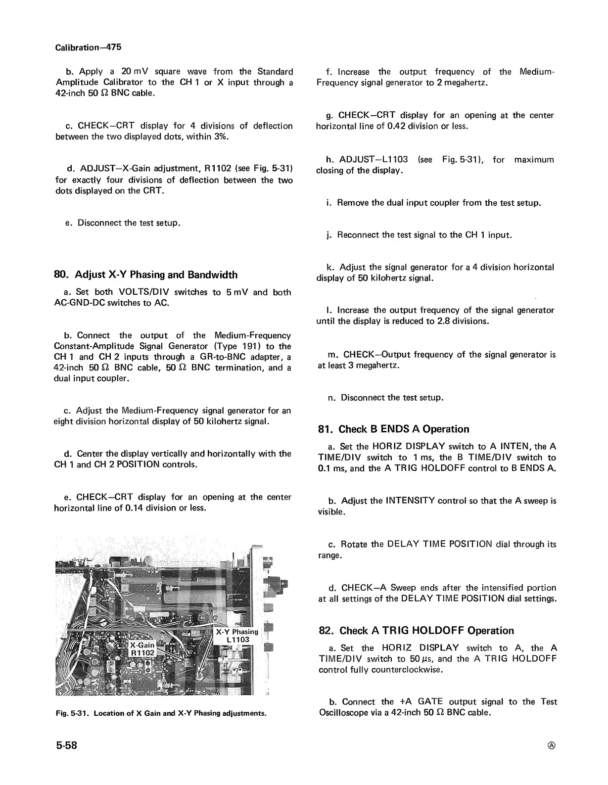
d. ADJUST—X-Gain adjustment, R1102 (see Fig. 5-31)
for exactly four divisions of deflection between the two
dots displayed on the CRT.
e. Disconnect the test setup.
80. Adjust X-Y Phasing and Bandwidth
a. Set both VOLTS/DIV switches to 5 mV and both
AC-GND-DC switches to AC.
b. Connect the output of the Medium-Frequency
Constant-Amplitude Signal Generator (Type 191) to the
CH 1 and CH 2 inputs through a GR-to-BNC adapter, a
42-inch 50 £2 BNC cable, 50 £2 BNC termination, and a
dual input coupler.
c. Adjust the Medium-Frequency signal generator for an
eight division horizontal display of 50 kilohertz signal.
d. Center the display vertically and horizontally with the
CH 1 and CH 2 POSITION controls.
e. CHECK—CRT display for an opening at the center
horizontal line of 0.14 division or less.
Fig. 5-31. Location of X Gain and X-Y Phasing adjustments.
f. Increase the output frequency of the Medium-
Frequency signal generator to 2 megahertz.
g. CHECK—CRT display for an opening at the center
horizontal line of 0.42 division or less.
h. ADJUST—L1103 (see Fig. 5-31), for maximum
closing of the display.
i. Remove the dual input coupler from the test setup.
j. Reconnect the test signal to the CH 1 input.
k. Adjust the signal generator for a 4 division horizontal
display of 50 kilohertz signal.
l. Increase the output frequency of the signal generator
until the display is reduced to 2.8 divisions.
m. CHECK—Output frequency of the signal generator is
at least 3 megahertz.
n. Disconnect the test setup.
81. Check B ENDS A Operation
a. Set the HORIZ DISPLAY switch to A INTEN, the A
TIME/DIV switch to 1 ms, the B TIME/DIV switch to
0.1 ms, and the A TRIG HOLDOFF control to B ENDS A.
b. Adjust the INTENSITY control so that the A sweep is
visible.
c. Rotate the DELAY TIME POSITION dial through its
range.
d. CHECK—A Sweep ends after the intensified portion
at all settings of the DELAY TIME POSITION dial settings.
82. Check A TRIG HOLDOFF Operation
a. Set the HORIZ DISPLAY switch to A, the A
TIME/DIV switch to 5 0ms, and the A TRIG HOLDOFF
control fully counterclockwise.
b. Connect the +A GATE output signal to the Test
Oscilloscope via a 42-inch 50 £2 BNC cable.
5-58
®