Calibration—475
c. Set the Test Oscilloscope TIME/DIV switch so that
the bottom portion of the waveform (holdoff time of the
+A GATE) is slightly less than one division.
d. Rotate the A TRIG HOLDOFF control clockwise
(not into the B ENDS A detent).
e. CHECK—For at least nine times increase in the
holdoff time of the +A GATE.
f. Set the A TRIG HOLDOFF control fully counter
clockwise.
CALIBRATOR, + GATES, AND
EXT Z-AXIS CALIBRATOR
Equipment Required
1. Medium-Frequency Constant-Amplitude Signal Genera- 4. BNC-T Connector
tor (Type 191)
2. Precision DC Voltmeter
3. GR-to-BNC Female Adapter
5. 42-inch 50 £2 BNC Cable (two)
6. Three-inch Screwdriver
Control Settings
Preset instrument controls to the settings given under
Preliminary Control Settings.
83. Adjust CALIBRATOR Amplitude
a. Connect the Precision DC Voltmeter between the
CALIBRATOR current loop and ground.
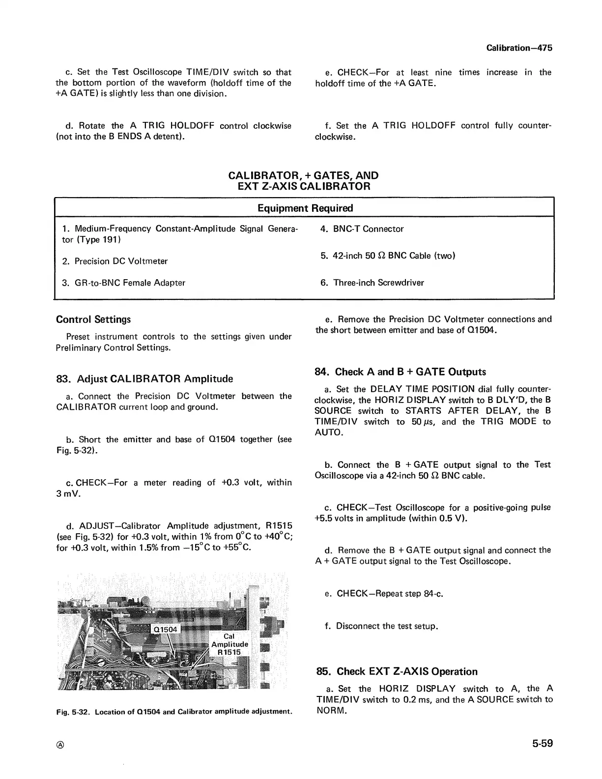
b. Short the emitter and base of Q1504 together (see
Fig. 5-32).
c. CHECK—For a meter reading of +0.3 volt, within
3 mV.
d. ADJUST—Calibrator Amplitude adjustment, R1515
(see Fig. 5-32) for +0.3 volt, within 1% from 0°C to +40°C;
for +0.3 volt, within 1.5% from —15°C to +55°C.
Fig. 5-32. Location of Q1504 and Calibrator amplitude adjustment.
e. Remove the Precision DC Voltmeter connections and
the short between emitter and base of Q1504.
84. Check A and B + GATE Outputs
a. Set the DELAY TIME POSITION dial fully counter
clockwise, the HORIZ DISPLAY switch to B DLY'D, the B
SOURCE switch to STARTS AFTER DELAY, the B
TIME/DIV switch to 50 ms, and the TRIG MODE to
AUTO.
b. Connect the B + GATE output signal to the Test
Oscilloscope via a 42-inch 50 12 BNC cable.
c. CHECK—Test Oscilloscope for a positive-going pulse
+5.5 volts in amplitude (within 0.5 V).
d. Remove the B + GATE output signal and connect the
A + GATE output signal to the Test Oscilloscope.
e. CHECK—Repeat step 84-c.
f. Disconnect the test setup.
85. Check EXT Z-AXIS Operation
a. Set the HORIZ DISPLAY switch to A, the A
TIME/DIV switch to 0.2 ms, and the A SOURCE switch to
NORM.
®
5-59