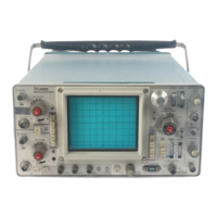
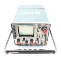
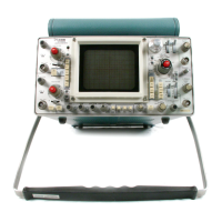
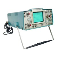
475 Service Page 3 of 6
Page 5-29
Fig. 5-6 and 5-7 replace with accompanying new photos.
CHANGE
Step lid
a portion to read - — between TP1395 (see new Fig. 5-6)
------
CHANGE
Step 12a
a portion to read — of the delay line (see new Fig. 5-7)-
Page 5-30
Fig. 5-8 replace with accompanying new photo.
Page 5-31
Fig. 5-9 replace with accompanying new photo.
Page 5-32
Fig. 5-11 and 5-12 replace with accompanying new photos.
Step 22a add to existing text:
Set CH-2 AC-GND-DC Switch to AC.
For SN Below B030000 in steps 23i and 23j change 100 mV
to read 250 mV.
Page 5-32 and 5-33
Page 5-32
23.
For SN B030000 and up, replace the existing steps 23
and 24 with the following steps. Refer to the accompanying
revised Figures for correct location of adjustments.
Adjust CH 1 and Vertical Output Gain (SN B030000-up)
a) Set the Vertical Mode Switch to CH 1, the CH 1
VOLTS/DIV switch to 2 mV and the CH 1 AC-GND-DC switch
to DC.
b) Adjust the STANDARD AMPLITUDE CALIBRATOR for a 10 mV
output.
c) Connect the STANDARD AMPL. CALIBRATOR to the CH 1 input.
C2/573


 To Next Page