475
Page 5 of 6
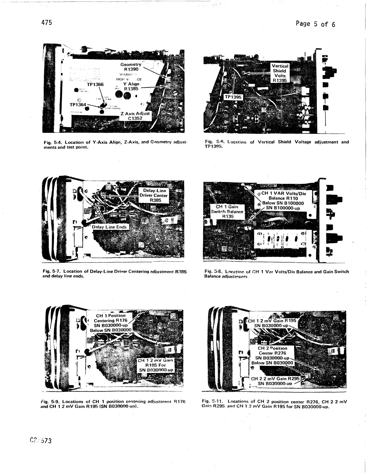
Fig. 5-4. Location of Y-Axis Align, Z-Axis, and Geometry adjust
ments and test point.
Fig. 5-ft. Location of Vertical Shield Voltage adjustment and
TP 1395.
Fig. 5-7. Location of Delay-Line Driver Centering adjustment R385
and delay line ends.
Fig, 5-S. Location of CH 1 Var Volts/Div Balance and Gain Switch
Balance adjustments.
Fig. 5-9. Locations of CH 1 position centering adjustment R176 Pig. 5-11. Locations of CH 2 position center R276, CH 2 2 mV
and CH 1 2 mV Gain R195 (SIM B030000 up). Gain R295 and CH 1 2 mV Gain R195 for SN B030000-up.
C?/573