HORIZONTAL AMPLIFIER
General
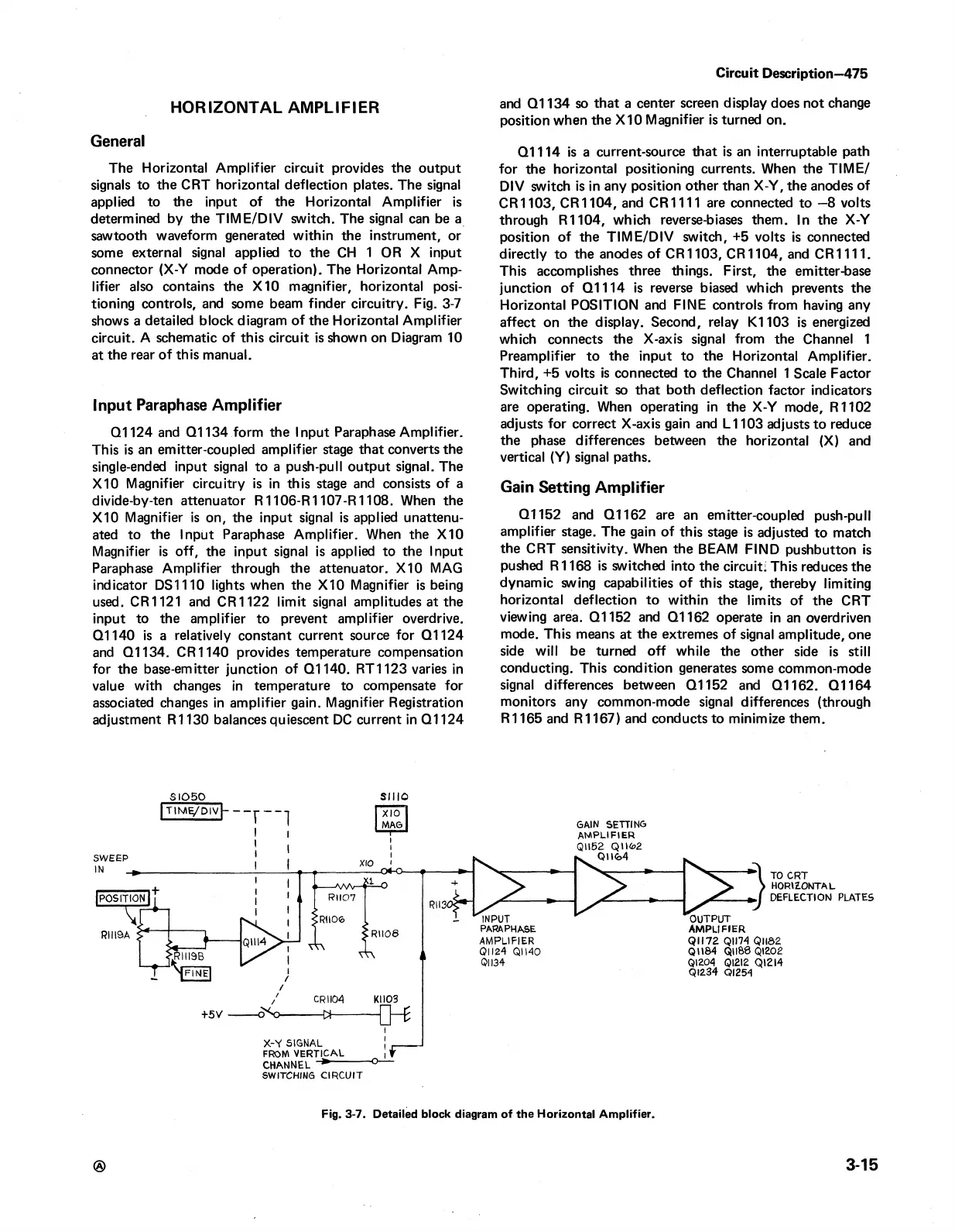
The Horizontal Amplifier circuit provides the output
signals to the CRT horizontal deflection plates. The signal
applied to the input of the Horizontal Amplifier is
determined by the TIM E /D IV switch. The signal can be a
sawtooth waveform generated within the instrument, or
some external signal applied to the CH 1 OR X input
connector (X-Y mode of operation). The Horizontal Amp
lifier also contains the X10 magnifier, horizontal posi
tioning controls, and some beam finder circuitry. Fig. 3-7
shows a detailed block diagram of the Horizontal Amplifier
circuit. A schematic of this circuit is shown on Diagram 10
at the rear of this manual.
Input Paraphase Amplifier
Q1124 and Q1134 form the Input Paraphase Amplifier.
This is an emitter-coupled amplifier stage that converts the
single-ended input signal to a push-pull output signal. The
X10 Magnifier circuitry is in this stage and consists of a
divide-by-ten attenuator R1106-R1107-R1108. When the
X10 Magnifier is on, the input signal is applied unattenu
ated to the Input Paraphase Amplifier. When the X I 0
Magnifier is off, the input signal is applied to the Input
Paraphase Amplifier through the attenuator. X10 MAG
indicator DS1110 lights when the X10 Magnifier is being
used. CR1121 and CR1122 limit signal amplitudes at the
input to the amplifier to prevent amplifier overdrive.
Q1140 is a relatively constant current source for Q1124
and Q1134. CR1140 provides temperature compensation
for the base-emitter junction of Q1140. RT1123 varies in
value with changes in temperature to compensate for
associated changes in amplifier gain. Magnifier Registration
adjustment R1130 balances quiescent DC current in Q1124
Circuit Description—475
and Q1134 so that a center screen display does not change
position when the X10 Magnifier is turned on.
Q1114 is a current-source that is an interruptable path
for the horizontal positioning currents. When the TIM E/
DIV switch is in any position other than X-Y, the anodes of
CR1103, CR1104, and CR 1111 are connected to —8 volts
through R1104, which reverse-biases them. In the X-Y
position of the TIM E/DIV switch, +5 volts is connected
directly to the anodes of CR1103, CR1104, and CR 1111.
This accomplishes three things. First, the emitter-base
junction of Q1114 is reverse biased which prevents the
Horizontal POSITION and FINE controls from having any
affect on the display. Second, relay K1103 is energized
which connects the X-axis signal from the Channel 1
Preamplifier to the input to the Horizontal Amplifier.
Third, +5 volts is connected to the Channel 1 Scale Factor
Switching circuit so that both deflection factor indicators
are operating. When operating in the X-Y mode, R1102
adjusts for correct X-axis gain and L 1103 adjusts to reduce
the phase differences between the horizontal (X) and
vertical (Y) signal paths.
Gain Setting Amplifier
Q1152 and Q1162 are an emitter-coupled push-pull
amplifier stage. The gain of this stage is adjusted to match
the CRT sensitivity. When the BEAM FIND pushbutton is
pushed R1168 is switched into the circuit: This reduces the
dynamic swing capabilities of this stage, thereby limiting
horizontal deflection to within the limits of the CRT
viewing area. Q1152 and Q1162 operate in an overdriven
mode. This means at the extremes of signal amplitude, one
side will be turned off while the other side is still
conducting. This condition generates some common-mode
signal differences between Q1152 and Q1162. Q1164
monitors any common-mode signal differences (through
R1165 and R1167) and conducts to minimize them.
S I0 5 0 SIIIO
®
3-15
Fig. 3-7. Detailed block diagram of the Horizontal Amplifier.
 Loading...


