Calibration—475
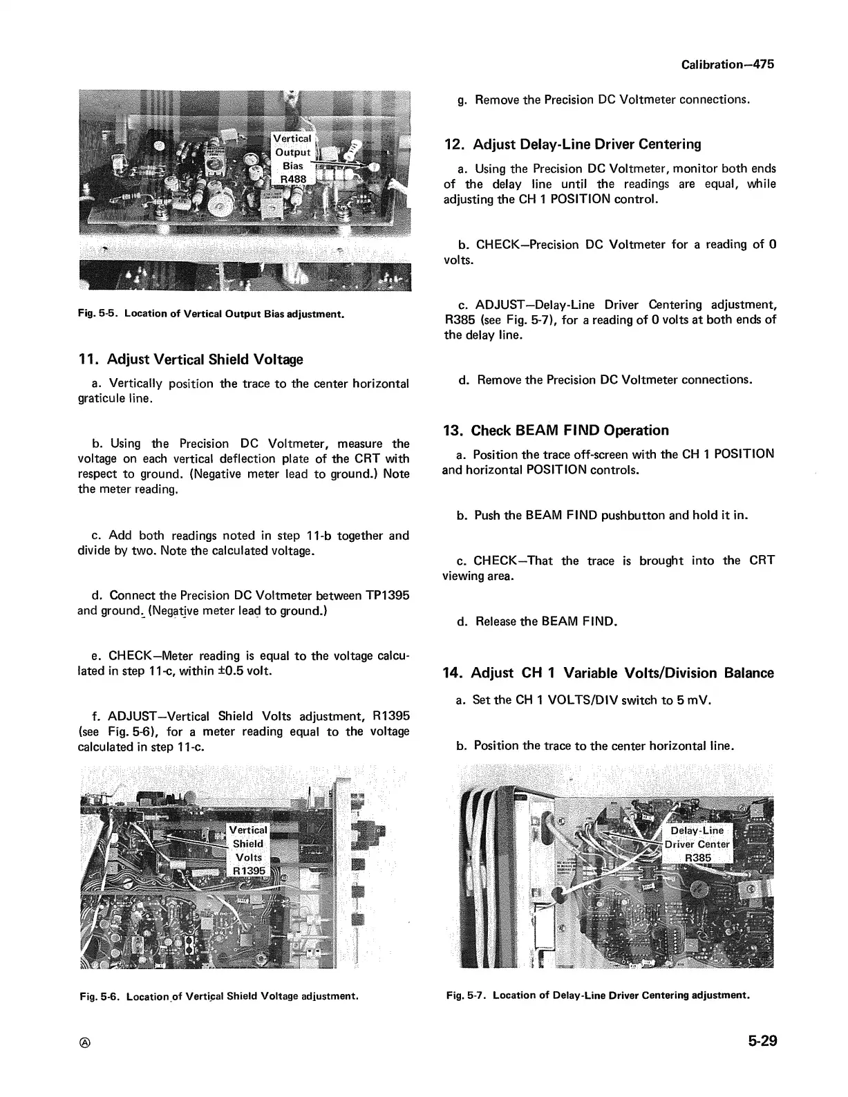
Fig. 5-5. Location of Vertical Output Bias adjustment.
11. Adjust Vertical Shield Voltage
a. Vertically position the trace to the center horizontal
graticule line.
b. Using the Precision DC Voltmeter, measure the
voltage on each vertical deflection plate of the CRT with
respect to ground. (Negative meter lead to ground.) Note
the meter reading.
c. Add both readings noted in step 11-b together and
divide by two. Note the calculated voltage.
d. Connect the Precision DC Voltmeter between TP1395
and ground^ (Negative meter lead to ground.)
g. Remove the Precision DC Voltmeter connections.
12. Adjust Delay-Line Driver Centering
a. Using the Precision DC Voltmeter, monitor both ends
of the delay line until the readings are equal, while
adjusting the CH 1 POSITION control.
b. CHECK—Precision DC Voltmeter for a reading of 0
volts.
c. ADJUST—Delay-Line Driver Centering adjustment,
R385 (see Fig. 5-7), for a reading of 0 volts at both ends of
the delay line.
d. Remove the Precision DC Voltmeter connections.
13. Check BEAM FIND Operation
a. Position the trace off-screen with the CH 1 POSITION
and horizontal POSITION controls.
b. Push the BEAM FIND pushbutton and hold it in.
c. CHECK—That the trace is brought into the CRT
viewing area.
d. Release the BEAM FIND.
e. CHECK—Meter reading is equal to the voltage calcu
lated in step 11-c, within ±0.5 volt. 14. Adjust CH 1 Variable Volts/Division Balance
a. Set the CH 1 VOLTS/DIV switch to 5 mV.
f. ADJUST—Vertical Shield Volts adjustment, R1395
(see Fig. 5-6), for a meter reading equal to the voltage
calculated in step 11-c. b. Position the trace to the center horizontal line.
if
Fig. 5-6. Location of Vertical Shield Voltage adjustment.
Fig. 5-7. Location of Delay-Line Driver Centering adjustment.
5-29