Calibration—475
c. CHECK—That the CH 1 UNCAL light turns on when
the VAR control is out of the detent position.
d. CHECK—CRT display for 2 divisions or less of trace
shift when rotating the CH 1 VAR control through its
range.
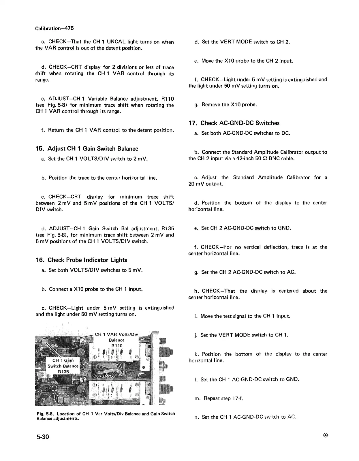
e. ADJUST—CH 1 Variable Balance adjustment, R110
(see Fig. 5-8) for minimum trace shift when rotating the
CH 1 VAR control through its range.
f. Return the CH 1 VAR control to the detent position.
15. Adjust CH 1 Gain Switch Balance
a. Set the CH 1 VOLTS/DIV switch to 2 mV.
b. Position the trace to the center horizontal line.
c. CHECK—CRT display for minimum trace shift
between 2 mV and 5 mV positions of the CH 1 VOLTS/
DIV switch.
d. ADJUST—CH 1 Gain Switch Bal adjustment, R135
(see Fig. 5-8), for minimum trace shift between 2 mV and
5 mV positions of the CH 1 VO LTS/DIV switch.
16. Check Probe Indicator Lights
a. Set both VOLTS/DIV switches to 5 mV.
b. Connect a X I0 probe to the CH 1 input.
c. CHECK—Light under 5 mV setting is extinguished
and the light under 50 mV setting turns on.
Fig. 5-8. Location of CH 1 Var Voits/Div Balance and Gain Switch
Balance adjustments.
d. Set the VERT MODE switch to CH 2.
e. Move the X I0 probe to the CH 2 input.
f. CHECK—Light under 5 mV setting is extinguished and
the light under 50 mV setting turns on.
g. Remove the X I0 probe.
17. Check AC-GND-DC Switches
a. Set both AC-GND-DC switches to DC.
b. Connect the Standard Amplitude Calibrator output to
the CH 2 input via a 42-inch 50 12 BNC cable.
c. Adjust the Standard Amplitude Calibrator for a
20 mV output.
d. Position the bottom of the display to the center
horizontal line.
e. Set CH 2 AC-GND-DC switch to GND.
f. CHECK—For no vertical deflection, trace is at the
center horizontal line.
g. Set the CH 2 AC-GND-DC switch to AC.
h. CHECK—That the display is centered about the
center horizontal line.
i. Move the test signal to the CH 1 input.
j. Set the VERT MODE switch to CH 1.
k. Position the bottom of the display to the center
horizontal line,
l. Set the CH 1 AC-GND-DC switch to GND.
m. Repeat step 17-f.
n. Set the CH 1 AC-GND-DC switch to AC.
®
5-30