Calibration—475
22. Adjust CH 2 Position Centering
a. Set the CH 2 VOLTS/DIV switch to 2 mV.
b. Move the test signal to the CH 2 input.
c. CHECK—The top of the CRT display can be posi
tioned below the center horizontal graticule line, and that
the bottom of the display can be positioned above the
center horizontal graticule line.
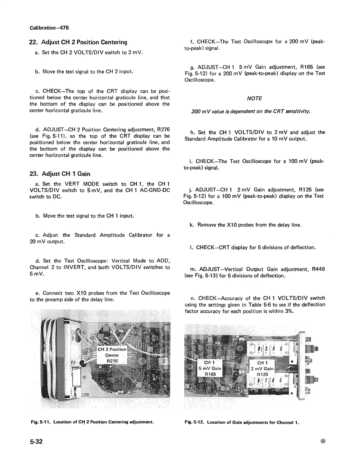
d. ADJUST—CH 2 Position Centering adjustment, R276
(see Fig. 5-11), so the top of the CRT display can be
positioned below the center horizontal graticule line, and
the bottom of the display can be positioned above the
center horizontal graticule line.
23. Adjust CH 1 Gain
a. Set the VERT MODE switch to CH 1, the CH 1
VOLTS/DIV switch to 5 mV, and the CH 1 AC-GND-DC
switch to DC.
b. Move the test signal to the CH 1 input.
c. Adjust the Standard Amplitude Calibrator for a
20 mV output.
d. Set the Test Oscilloscope: Vertical Mode to ADD,
Channel 2 to INVERT, and both VO LTS/DIV switches to
5 mV.
e. Connect two X I0 probes from the Test Oscilloscope
to the preamp side of the delay line.
Fig. 5-11. Location of CH 2 Position Centering adjustment.
f. CHECK—The Test Oscilloscope for a 200 mV (peak-
to-peak) signal.
g. ADJUST—CH 1 5 mV Gain adjustment, R165 (see
Fig. 5-12) for a 200 mV (peak-to-peak) display on the Test
Oscilloscope.
NOTE
200 m V value is dependent on the CRT sensitivity.
h. Set the CH 1 VOLTS/DIV to 2 mV and adjust the
Standard Amplitude Calibrator for a 10 mV output.
i. CHECK—The Test Oscilloscope for a 100 mV (peak-
to-peak) signal.
j. ADJUST—CH 1 2 mV Gain adjustment, R125 (see
Fig. 5-12) for a 100 mV (peak-to-peak) display on the Test
Oscilloscope.
k. Remove the X I0 probes from the delay line.
I. CHECK—CRT display for 5 divisions of deflection.
m. ADJUST—Vertical Output Gain adjustment, R449
(see Fig. 5-13) for 5 divisions of deflection.
n. CHECK-Accuracy of the CH 1 VO LTS/DIV switch
using the settings given in Table 5-6 to see if the deflection
factor accuracy for each position is within 3%.
5-32
Fig. 5-12. Location of Gain adjustments for Channel 1.