Calibration—475
TABLE 5-6
Vertical Deflection Accuracy
24. Adjust CH 2 Gain
a. Set the VERT MODE switch to CH 2, the CH 2
VOLTS/DIV switch to 5 mV, and the AC-GND-DC switch
to DC.
b. Move the test signal to the CH 2 input.
c. Adjust the Standard Amplitude Calibrator for a
20 mV output.
d. CHECK—CRT display for 4 divisions of deflection,
within 3%.
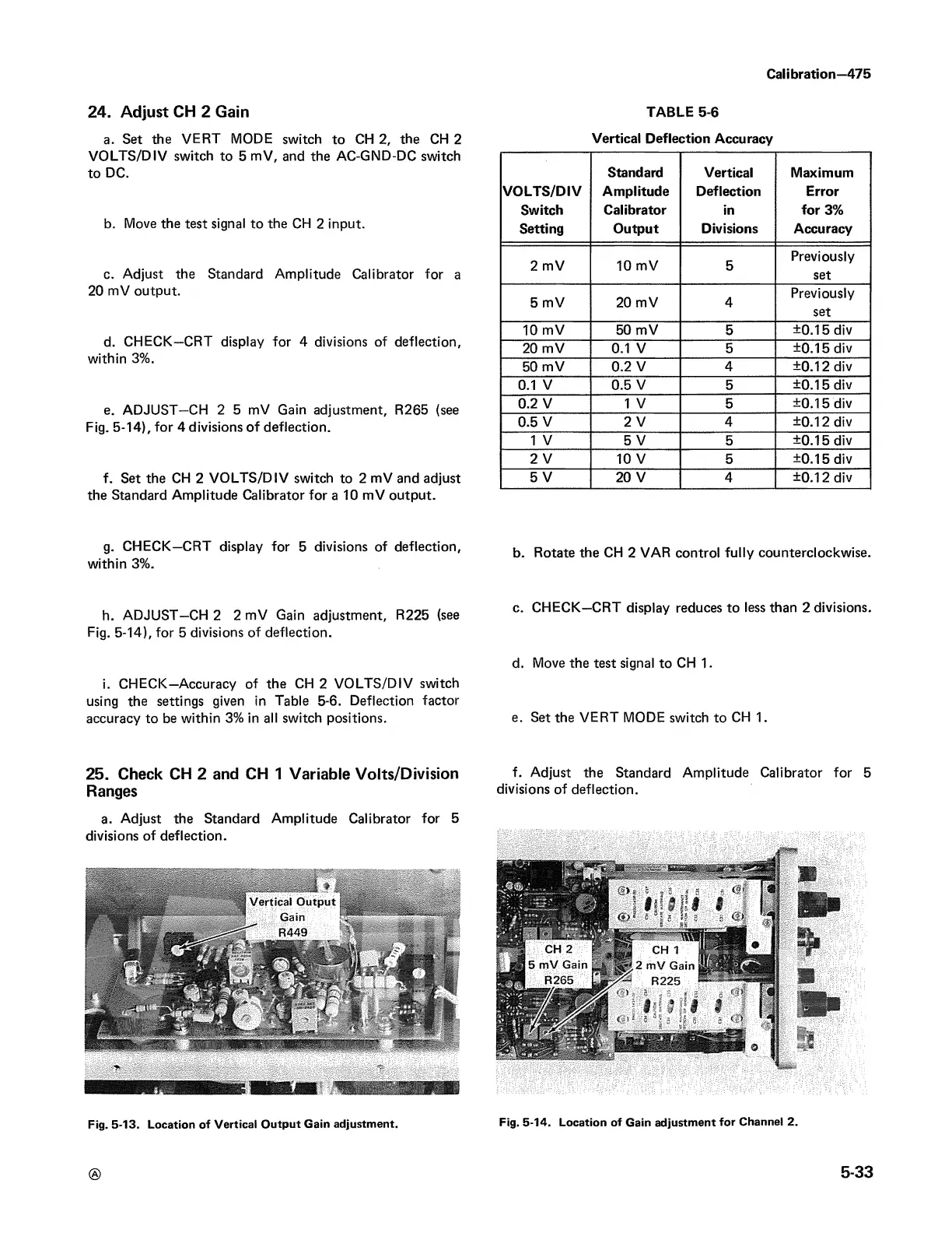
e. ADJUST—CH 2 5 mV Gain adjustment, R265 (see
Fig. 5-14), for 4 divisions of deflection.
f. Set the CH 2 VOLTS/DIV switch to 2 mV and adjust
the Standard Amplitude Calibrator for a 10 mV output.
g. CHECK—CRT display for 5 divisions of deflection,
within 3%.
h. ADJUST—CH 2 2 mV Gain adjustment, R225 (see
Fig. 5-14), for 5 divisions of deflection.
i. CHECK—Accuracy of the CH 2 VO LTS/DIV switch
using the settings given in Table 5-6. Deflection factor
accuracy to be within 3% in all switch positions.
Standard
Vertical
Maximum
VO LTS/DIV Amplitude
Deflection
Error
Switch
Calibrator
in
for 3%
Setting Output
Divisions
Accuracy
2 mV 10 mV
5
Previously
set
5 mV
20 mV
4
Previously
set
10 mV 50 mV
5
±0.15 div
20 mV
0.1 V
5
±0.15 div
50 mV
0.2 V
4
±0.12 div
0.1 V 0.5 V
5
±0.15 div
0.2 V 1 V
5
±0.15 div
0.5 V
2 V 4
±0.12 div
1 V
5 V 5
±0.15 div
2 V
10 V
5
±0.15 div
5 V 20 V
4
±0.12 div
b. Rotate the CH 2 VAR control fully counterclockwise.
c. CHECK—CRT display reduces to less than 2 divisions.
d. Move the test signal to CH 1.
e. Set the VERT MODE switch to CH 1.
25. Check CH 2 and CH 1 Variable Volts/Division f- Adjust the Standard Amplitude Calibrator for 5
Ranges divisions of deflection.
a. Adjust the Standard Amplitude Calibrator for 5
divisions of deflection.
Fig. 5-13. Location of Vertical Output Gain adjustment.
®
5-33
Fig. 5-14. Location of Gain adjustment for Channel 2.