Calibration—475
g. Rotate the CH 1 VAR control fully counterclockwise.
h. CHECK—CRT display reduces to less than 2 divisions.
i. Return the VAR controls to the detent position.
26. Check ADD Mode Operation
a. Set both VO LTS/DIV switches to 5 mV and both
AC-GND-DC switches to DC.
b. Connect the Standard Amplitude Calibrator output to
both channel inputs via a dual input coupler.
c. Adjust the Standard Amplitude Calibrator for a
10 mV output.
d. Set the VERT MODE switch to ADD.
e. CHECK—For 4 divisions of deflection, within 0.12
division.
27. Check Compression and Expansion
a. Set the CH 2 AC-GND-DC switch to GND and the
VE RT MOD E switch to CH 1.
b. Adjust the CH 1 VAR control for 2 divisions of
deflection centered about the center horizontal line.
c. Position the top of the display to the top graticule
line.
d. CHECK—CRT display for 0.1 division or less of
compression or expansion.
e. Position the bottom of the display to the bottom
graticule line.
f. CHECK—CRT display for 0.1 division or less of
compression or expansion.
g. Return the CH 1 VAR control to the detent position.
h. Disconnect the test setup.
5-34
28. Check ALT Mode Operation
a. Set the VERT MODE switch to ALT and the A
LEVEL control fully clockwise.
b. Position the two traces 2 divisions apart.
c. CHECK—That the sweeps alternate at all settings of
the A TIM E /D IV switch, except X-Y.
29. Check CHOP Mode Operation
a. Set the A T IM E /D IV switch to 0.2 ms, the A SOURCE
switch to NORM, the A SLOPE switch to +, the VERT
MODE switch to CHOP, and both AC-GND-DC switches to
GND.
b. Position the two traces 4 divisions apart.
c. Adjust the A LEVEL control for a stable display.
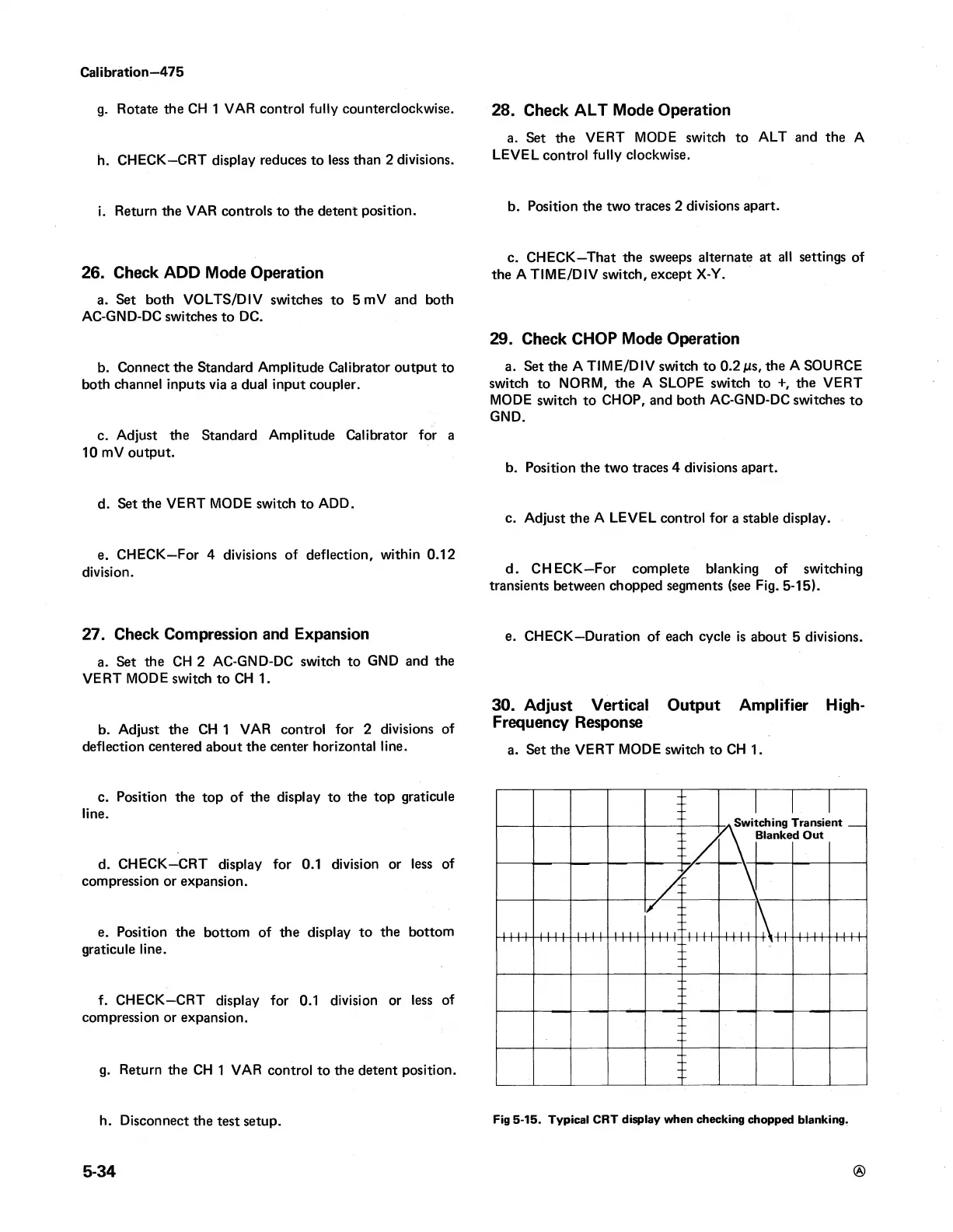
d. CHECK—For complete blanking of switching
transients between chopped segments (see Fig. 5-15).
e. CHECK—Duration of each cycle is about 5 divisions.
30. Adjust Vertical Output Amplifier High-
Frequency Response
a. Set the VERT MODE switch to CH 1.
Fig 5-15. Typical CRT display when checking chopped blanking.