Calibration—475
b. Connect the preamp end of the delay line to the
output of the Signal Insertion Unit (067-0676-00).
c. Connect the Signal Insertion Unit to +15 volts and —8
volts from the 475.
d. Connect the Fast-Rise High-Amplitude Pulse Genera
tor (Type 109) to the Signal Insertion Unit via a 50 12 5 ns
GR cable, a X5 GR attenuator Signal Pickoff Unit (Type
CT-3), and a GR-to-BNC adapter.
e. Connect the 10% output BNC connector of the Signal
Pickoff Unit (Type CT-3) to the A External Trigger input
via an 18-inch 50 12 BNC cable and a 50 12 BNC termina
tion.
f. Adjust the Pulse Generator for 5 divisions of deflec
tion, + Polarity.
g. CHECK—CRT display for flat-top waveform with no
more than 10% overshoot on the leading edge.
h. ADJUST—C450, R450, C466, R466, C470, R470
(see Fig. 5-16), for best flat-top waveform.
i. CAL A ID —Adjust C450 and R450 for minimum
aberrations; C466 and R466 for flat response over the first
5 ns; C470 and R470 for flat response over the first 15 ns.
R450 should be adjusted as far counterclockwise as
possible.
j. INTERACTION-Between all adjustments in this step.
Re-adjust for best flat-top response.
Fig. 5-16. Location of vertical output high-frequency adjustments.
k. Disconnect the test setup and reconnect the Delay
Line to the Vertical preamp.
31. Adjust High-Frequency Compensation
a. Connect the fast-rise output of the Square-Wave
Generator (Type 106) to the CH 1 input via a 42-inch 50 12
BNC cable and a 50 12 BNC termination.
b. Set the CH 1 AC-GND-DC switch to DC and the
VO LTS/DIV switch to 5 mV.
c. Adjust the Square-Wave Generator for a 5 division
display of a 10 kHz signal.
d. CHECK—CRT display for flat-top waveform within
+4%, —4%f or a total of 4% aberrations.
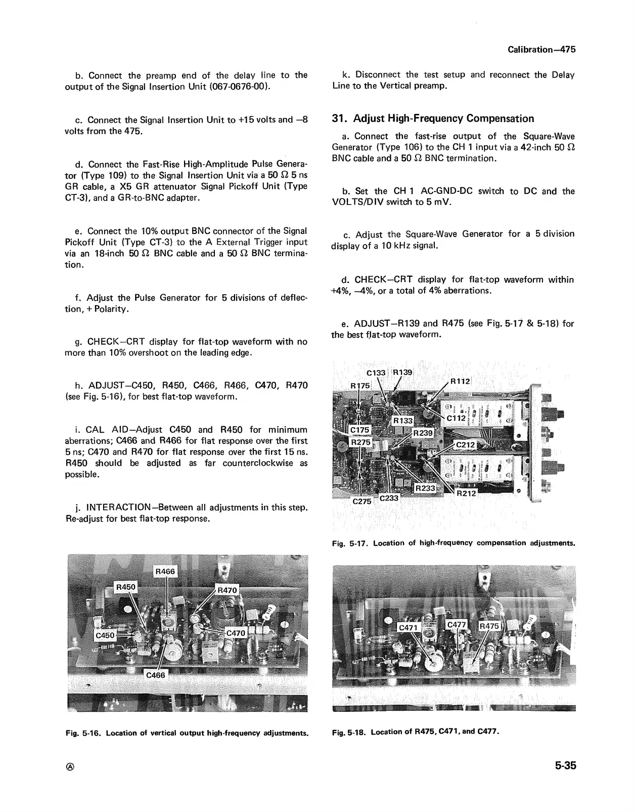
e. ADJUST—R139 and R475 (see Fig. 5-17 & 5-18) for
the best flat-top waveform.
C l33 -H I39
Fig. 5-17. Location of high-frequency compensation adjustments.
Fig. 5-18. Location of R475, C471, and C477.
5-35