Calibration—475
c. CHECK—That a stable display can just be obtained by
rotating the B LEVEL control.
d. Adjust the Medium-Frequency signal generator to
increase the CRT display to 0.35 division.
e. ADJUST—B Trigger Sensitivity adjustment, R785 {see
Fig. 5-20) so that a stable display can just be obtained by
rotating the B LEVEL control.
40. Adjust B Trigger Centering and Symmetry
a. Set both TIM E/D IV switches to 10ms, both LEVEL
controls to 0, the CH 1 VO LTS/DIV switch to 50 mV, and
the B SOURCE switch to NORM.
b. Adjust the Medium-Frequency signal generator for a 2
division display of a 350 kilohertz signal.
c. Vertically center the display about the center hori
zontal graticule line.
d. CHECK—CRT display begins at the same vertical
point in both slopes of the displayed waveform.
e. ADJUST—B Trigger Symmetry adjustment, R767 (see
Fig. 5-20), so that the trace begins at the same point in
both slopes of the displayed waveform.
f. ADJUST—B Trigger Centering adjustment, R754 (see
Fig. 5-20), for the trigger point of the display to be at the
graticule center.
g. CAL A ID —A gap equal to 35 mV should exist
between the + and — trigger points.
41. Adjust A Trigger Centering and Symmetry
a. Set the HORIZ DISPLAY switch to A and the A
SOURCE switch to NORM.
b. CHECK-CRT display begins at the same vertical
point in both slopes of the displayed waveform.
c. AD JUST -A Trigger Symmetry adjustment, R547 (see
Fig. 5-20), so that the trace begins at the same point in
both slopes of the displayed waveform.
d. ADJUST—A Trigger Centering adjustment, R534 (see
Fig. 5-20), for the trigger point of the display to be at the
graticule center.
e. CAL A ID —A gap equal to 35 mV should exist
between the + and — trigger points.
42. Adjust Trigger DC Balance
a. Set the A COUPLING switch to DC, the A SOURCE
switch to NORM, and the A LEVEL control to 0.
b. Adjust the Medium-Frequency signal generator for a
0.3 division display.
c. Position the display to the vertical center of the
graticule viewing area.
d. CHECK—That a stable display can be obtained on
both slopes of the displayed waveform.
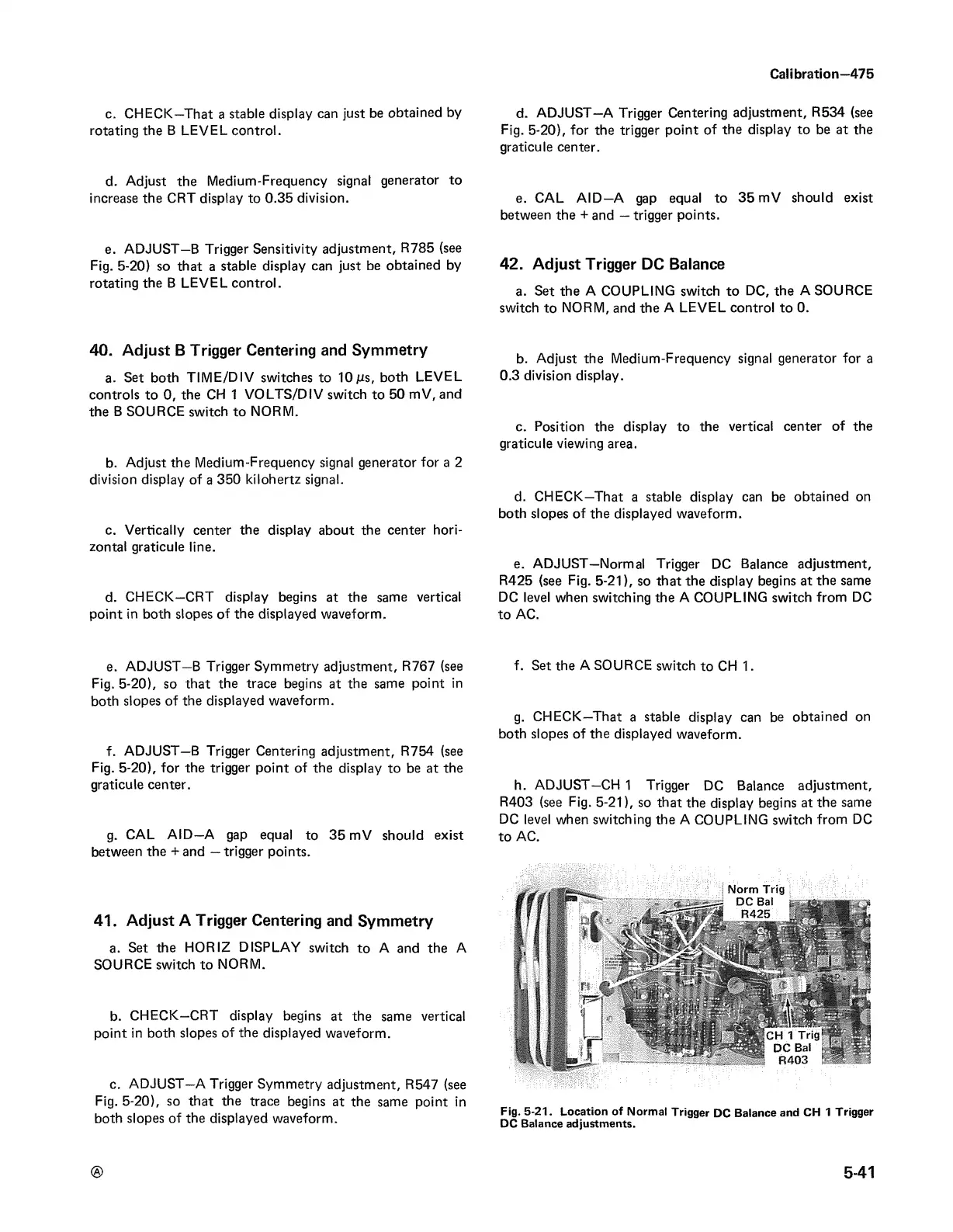
e. ADJUST—Normal Trigger DC Balance adjustment,
R425 (see Fig. 5-21), so that the display begins at the same
DC level when switching the A COUPLING switch from DC
to AC.
f. Set the A SOURCE switch to CH 1.
g. CHECK—That a stable display can be obtained on
both slopes of the displayed waveform.
h. ADJUST—C H I Trigger DC Balance adjustment,
R403 (see Fig. 5-21), so that the display begins at the same
DC level when switching the A COUPLING switch from DC
to AC.
Fig. 5-21. Location of Normal Trigger DC Balance and CH 1 Trigger
DC Balance adjustments.
®
541
 Loading...


