TRIGGER SYSTEM CALIBRATION
Calibration—475
Equipment Required
1. Standard Amplitude Calibrator (067-0502-01).
8. GR-to-BNC Female Adapter.
2. High-Frequency Constant-Amplitude Signal Generator
9. 42-inch 50 £2 BNC Cable.
(067-0532-01).
10. 18-inch 50 £2 BNC Cable (two).
3. Medium-Frequency Constant-Amplitude Signal Genera
tor (Type 191).
11. X I0 BNC Attenuator
4. Low-Frequency Sine-Wave Generator (General Radio
1310-A).
12. X2 BNC Attenuator
13. BNC-T Connector
5. Time-Mark Generator (Type 2901).
14. 50 £2 BNC Termination (two).
6. 50 £2 Signal Pickoff Unit (Type CT-3).
15, Dual Input Coupler (two).
7. 50 £2 5 nanosecond GR Cable.
16. Three-inch Screwdriver.
Control Settings
Preset instrument controls to the settings given under
Preliminary Control Settings except as follows:
CH 1 VOLTS/DIV 10 mV
A SOURCE EXT
A COUPLING AC
A LEVEL 0
38. Adjust A Trigger Sensitivity
a. Connect the output of the Medium-Frequency
Constant-Amplitude Signal Generator (Type 191) to the A
and B External Trigger inputs via a 50 £2 5 ns GR cable,
50 £2 Signal Pickoff Unit (Type CT-3) thru output, GR-to-
BNC adapter, X10 BNC attenuator, 50 £2 BNC termination,
and a dual input coupler.
b. Connect the 10% BNC output connector of the Signal
Pickoff Unit to the CH 1 and CH 2 inputs via an 18-inch
50 £2 BNC cable, a 50 £2 BNC termination, and a dual input
coupler.
c. Adjust the Medium-Frequency signal generator output
for a 3 division display of a 350 kHz signal.
d. Turn the CH 1 VOLTS/DIV switch to 0.1 V.
e. CHECK—That a stable display can be obtained by
rotating the A LEVEL control.
f. Adjust the Medium-Frequency signal generator to
increase the CRT display to 0.35 division.
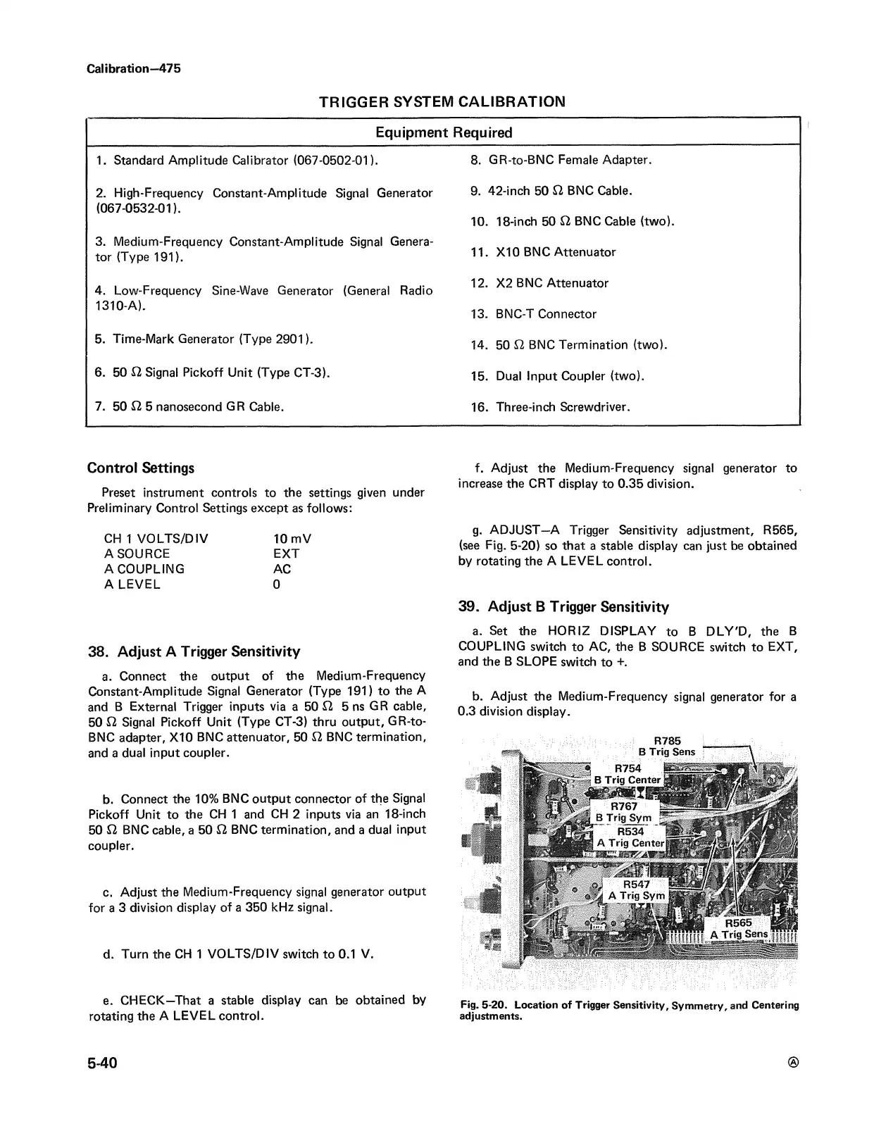
g. ADJUST—A Trigger Sensitivity adjustment, R565,
(see Fig. 5-20) so that a stable display can just be obtained
by rotating the A LEVEL control.
39. Adjust B Trigger Sensitivity
a. Set the HORIZ DISPLAY to B DLY'D, the B
COUPLING switch to AC, the B SOURCE switch to EXT,
and the B SLOPE switch to +.
b. Adjust the Medium-Frequency signal generator for a
0.3 division display.
R785
Fig. 5-20. Location of Trigger Sensitivity, Symmetry, and Centering
adjustments.
5-40