CFG253 Performance Verification & Adjustment Procedures
Page 8 of 19 Procedure #: CP1005 Revision: A
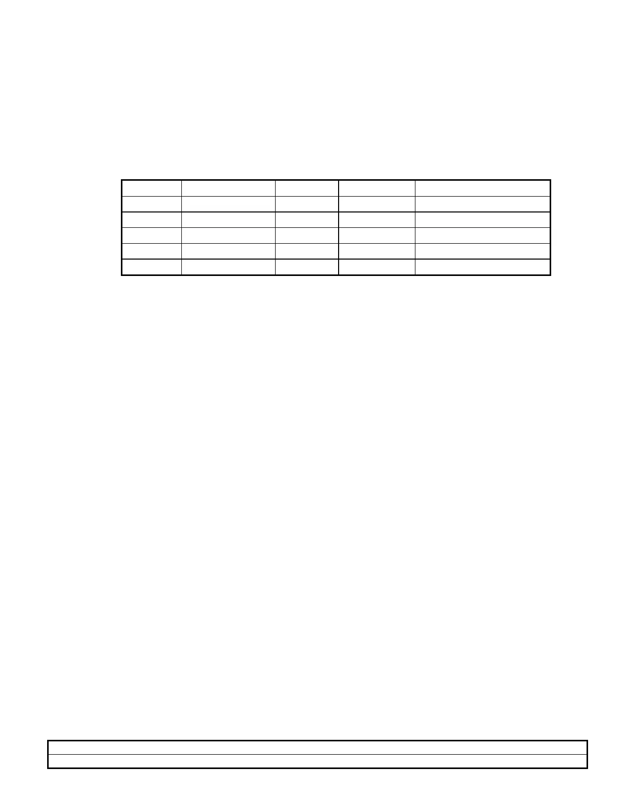
j. Repeat steps d and e to verify the 50 % duty cycles for the settings in Table 4.
Table 4
RANGE FREQ. DIAL FREQ/10 TIME/DIV RESULT
1K 3.0 OUT 20uSec 50 % Duty Cycle
1K 0.3 OUT 0.2mSec 50 % Duty Cycle
1K 0.3 IN 2 MSec 50 % Duty Cycle
100K 0.3 OUT 2 uSec 50 % Duty Cycle
1M 0.3 IN 2 uSec 50 % Duty Cycle
5. SYNC (TTL) OUTPUT
a. Set-Up:
AMPLITUDE CW
RANGE 1K
FUNCTION Triangle
VOLTS OUT Button Out
FREQ/10 Button Out
FREQ DIAL 3.0
b. Test Scope Set-Up:
Volts/Div 1 V
Time/Div 0.2 mSec
c. Connect SYNC/TTL OUTPUT directly to the test scope vertical input via a coax
cable (without the 50 ohm terminator).
d. Check the test scope for a display of approximately 4 volts (4 divisions).
e. Repeat step d with the FUNCTION set to Square Wave and Sine Wave.

 Loading...


